Continue to Site

Eng-Tips is the largest engineering community on the Internet

Intelligent Work Forums for Engineering Professionals

  • Congratulations waross on being selected by the Eng-Tips community for having the most helpful posts in the forums last week. Way to Go!

stresses in framed structures

chthulu

Student
May 7, 2025
6
Hi,
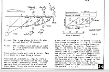
In the picture that follows, is fig 9 correct?
Using the scale in pounds shown there, the 70LBS line seems to be correct, where line a seems to be more or less 110 lbs and line b seems to be more or less 130 lbs, but using trigonometry I got something else for a and b.
So, is it possible to get a and b through trigonometry?
If you draw the line for the 70lbs according to the scale in pounds, how do you know where to stop when drawing a? or b? if you start from b.
I mean line a could be any length and fig 8 does not indicate how long line a should be.
What would be the best way to add the sketch of fig 8 together?
I really do not understand even how the 180 and 230 lbs are get.
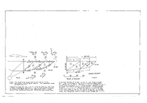
stress diagram.png
 
Replies continue below

Recommended for you

More info is likely available at www.homebuiltairplanes.com/forums/...


Your 'worked/partially intact figure' came from pg. 24... this left me scratching my head.

1746653407968.png

There is a 'CAUTION' about using Beaujon's manual for design, posted in the following thread on the Hombuiltairplane.com/forums...
 
I can not read that post, since they changed the forum and made it private, I not going to give them money.

Anyway the caution most probably has nothing to do with what I asked.
 
I'd be very wary of using a reference that labels a force diagram as a stress diagram.

Anyway he's constructed a Cremona/Maxwell diagram . This is good. I'm not crazy about his notation, should have used Bow's.

The key to determining the forces in a and b is shown in the little triangle at the top right. The vertical component of 70 lbf can only be provided by b, which then generates a tension in a to react the horizontal component of b.

The force in each member is purely axial, hence must be aligned with the geometry of that member.
 
Last edited:
I don't know this method, but the load in the rightmost member "b" is not 70 lbs, it's vertical component is.
I don't get the stress diagram from the truss geometry ... to show the load is member "a" at the left side of the stress/load graphic just seems so "wrong" (or certainly non-intuitive).

The reaction at A (and so at B too) is easily calculated (moments about B). The vertical reaction at B is 70 lbs.

Sure you can use force polygons, and so solve each joint. but the math to do this isn't hard.

Old methods like this are not gospel, they were developed a long time ago when tools we have (like excel and trig) were not so easy to use.
Sure, there is a place for them, but I would learn them as an adjunct to modern methods rather than as the way to solve a problem.
 
Sorry... guys about HBA reference... I've been a member 'forever'... here are some excerpts...

Home or this specific page
Tubing Connections I was bouncing around the internet and was happy to find a website that is sharing his work. He wasnt the most accomplished engineer ( was a real estate agent ) but he had the best imagination
and was willing to put ideas on paper far ahead of people doing anything similar.
Apparently they are publishing/sharing his book "How to Build Ultralights."
I talked to him a few decades ago and he said he spent hundreds of hours
in libraries doing the research for his book. Flipping through his paper napkin
design ideas made me feel like a kid again. With todays technology and materials more and more of his ideas should be doable.
----------------------

I haven't stayed in a Holiday Inn in a really long time, but my advice is to approach that stuff on that tubing connections page with extreme caution. No doubt it could work for a shade canopy in your back yard, but I wouldn't trust it in an a/c.
ex: the eyebolt example loads the through-bolt in bending; tension on the eyebolt will eventually fail the through-bolt.
ex: there's a long, ongoing thread on this site right now about how difficult it is to bond anything to aluminum for actual structure

Perhaps the a/c he designed presented such low loads on the joints that there was never a failure, but if true, it would seem to indicate that the structure was heavier than needed.
----------------------

RVCharlie is completely right. Herbert was a real estate agent with imagination. You should not take ANYTHING he says as authoritative.... I dont however think that it is a mistake to follow his thinking as possible alternatives that could prove to be good or bad. He wrote about ultralights before people were building them and in that regard he was visionary in my opinion and he made attempts to research and qualify ... but question everything you read. Indeed a lot of his
suggestions are more hardware store type solutions for farm implements and yes they will definitely be heavier than possible but also usually cheaper and simple. Think WeedHopper.
An eyebolt solution can sometimes be acceptable as like anything else you design to a load plus some cushion for safety etc and add a little more for good measure and maybe you added some weight and saved some time and maybe money. You are the designer now. I just wanted to share Beaujon' s work as entertainment.

xxxxxxxxxxxxxxxxxxx

I have attached the Beaujon 'design document'... he is deceased. CAUTION... lots of sketchy info.
 

Attachments

  • How to Build Ultralights~Herbert Beaujon~CAUTION.pdf
    5.7 MB · Views: 3
Thanks, I got that pdf, but I was puzzled by that page, since I could not find anything like that about a fuselage.
 
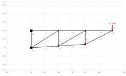
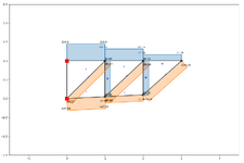
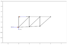
Now I used the online truss calculator and I got different results: (The default for the calculator is kN)
Nodes.pngAxial Force.pngReactions.png
 
can you show dimensions ? length is easy to deduce, I calculate pt7 at (2, 0.1) ?

when you're learning these methods, I'd suggest simplifying the structure (like make the lower chord parallel with the upper, use regular bay widths, ...);
then tweek these simpler models to get what you really want.
 
Last edited:
what dimensions? there are no dimensions. Look at the picture at the top, it is all based on Cremona/Maxwell diagram, so no dimensions. However, I realized that when I used the online truss calculator, I should have put the same dimensions as fig. 9, that means printing the page and then check all the dimensions I get from fig. 9 with a ruler.
 
Eyeballing it the right hand triangle, b is roughly 2^.5*70, and a is roughly 70. Yes changing the dimensions will change the forces in the members.
 

Part and Inventory Search

Sponsor