Continue to Site

Eng-Tips is the largest engineering community on the Internet

Intelligent Work Forums for Engineering Professionals

  • Congratulations cowski on being selected by the Eng-Tips community for having the most helpful posts in the forums last week. Way to Go!

Gap in a feature of size

aniiben

Mechanical
May 9, 2017
165
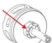
I have a faucet plastic component which has gaps/ interruptions along the circumference of an outside diameter. I cannot share the entire part, but something which is very similar is shown below. The outside diameter has 8 gaps around the 360° degrees which creates 8 arcs.
How can I define those 8 arcs related with a datum reference frame ?
I am using ASME 2009 (or with a note I can use 2018). I know I can use profile and position, but my question is:
Can I use CF- continuous feature per 2009 or 2018 with position ?
Can I use 8X size (.500±.015) and position?
(Profile and phantom circle is not much liked in my general industry- hence I will leave it to the last resort :eek: )
QFFCF - Copy.jpg
 
Replies continue below

Recommended for you

Your question is best asked of your inspectors.

In the example you are pointing at the edge between two nominally contiguous features.

Without CF individual sub-arcs won't really be features of size, so that's the only option.

I would be more likely to use total runout than position for an item like is pictured, but probably the real part is not like the picture, for simplification purposes.

3DDave,

Runout option has been explored before, but since this feature it is not easy accessible (nor can rotate due to other features involved) this runout option fall by the wayside.
So which option would you prefer:

CF + position on the phantom circle
OR
8x .500±.015 + 8x position to main datum reference frame
OR
8x .500±.015 + position on the phantom circle
 
Frankly it sounds like you are hostage to your own QA and need to ask them. I don't prefer any of those options because I expect it has nothing to do with part function. It's like asking what speed a car should go, but neglecting to say on what road, race track, or drag strip. I'm sure the actual function and the way the tolerances are to be allocated across all the parts is a corporate secret, so I won't be able to help you there.
 
Frankly it sounds like you are hostage to your own QA and need to ask them. I don't prefer any of those options because I expect it has nothing to do with part function. It's like asking what speed a car should go, but neglecting to say on what road, race track, or drag strip. I'm sure the actual function and the way the tolerances are to be allocated across all the parts is a corporate secret, so I won't be able to help you there.

I am confident that the actual function, design intent and the datum reference frame are adequately covered. The question I have, at this time, is how to define in ASME the pattern of those arcs? What would be the best / standardized method?
 
The best one may be CF. You want to explicity define the separate surfaces as a single feature.

You already know that. But if your QA doesn't like it, you will just choose something else.

Ask you QA group what they would do differently for each of the three methods.

All of those methods are standardized. Some are more explicit. 8X arcs is problematic as finding individual centers of small arcs is problematic.
 
The question I have, at this time, is how to define in ASME the pattern of those arcs?
These are not pattern of the arc. They are part of a circle or cylindrical surface that is interrupted by the slots (feature of size).
 
The best one may be CF. You want to explicity define the separate surfaces as a single feature.

You already know that. But if your QA doesn't like it, you will just choose something else.

Ask you QA group what they would do differently for each of the three methods.

All of those methods are standardized. Some are more explicit. 8X arcs is problematic as finding individual centers of small arcs is problematic.
3DDave,
I have to disagree with you. I don't think all 3 methods are standardized.
I've seen CF applied to profile, but never applied to position.
And could you please explain what's the difference between 8x and 8x position versus CF and position?
 
Is CF in the standard? That is standardized.

3.10 CONTINUOUS FEATURE
continuous feature: two or more interrupted features
designated with a “CF” symbol, indicating they are to
be considered as a single feature.
Can position be applied to a single feature?

3.11 CONTINUOUS FEATURE OF SIZE
continuous feature of size: two or more regular features of
size or an interrupted regular feature of size that is designated
with a “CF” symbol, indicating they are to be considered
as a single regular feature of size.
Can position be applied to a feature of size?

This is in the standard. It is standardized. Perhaps you mean, there is no silver platter example? It doesn't matter what one has "seen."
 
Will those 3 proposed solutions provide the same mathematical definition ?
If not, what would be the differences between them?

The best one may be CF. You want to explicity define the separate surfaces as a single feature.

You already know that. But if your QA doesn't like it, you will just choose something else.

Ask you QA group what they would do differently for each of the three methods.

All of those methods are standardized. Some are more explicit. 8X arcs is problematic as finding individual centers of small arcs is problematic.

Your question is best asked of your inspectors.

In the example you are pointing at the edge between two nominally contiguous features.

Without CF individual sub-arcs won't really be features of size, so that's the only option.

I would be more likely to use total runout than position for an item like is pictured, but probably the real part is not like the picture, for simplification purposes.

Is it really a good idea to ask each supplier which method they would prefer? (we are sending those parts for quotes/ be made by differnt suppliers)
I might get very different answers, don't you think?

Again, I would like to focus on the diferences between them, if possible.
 
Is it really good to talk to suppliers? No, leave everything up to the last minute when they call and tell you the parts are ready, but they didn't understand the requirements and the parts don't fit because they figured it meant something different than you thought it did.

If you get different answers then you know there is either a problem with the suppliers or a problem with the design.

The difference between them is whatever QA says they think the difference is. It's people who are doing the interpreting. If THEY think there is a difference there is a difference. Until ASME makes a single software reference interpreter for the analysis and simulation of their stupidly written standard it will always require calling up QA to see what they are going to do for odd cases. If it was up to the standard, you would use profile and runout. But you say your people don't like profile and cannot use runout; I guess it is accessible enough to reach for size and position, but no other measurement.

Y14.5 isn't a magic formula to make problems with QA not talking with you, and vice versa, go away.
 
The difference between them is whatever QA says they think the difference is. It's people who are doing the interpreting. If THEY think there is a difference there is a difference. Until ASME makes a single software reference interpreter for the analysis and simulation of their stupidly written standard it will always require calling up QA to see what they are going to do for odd cases. If it was up to the standard, you would use profile and runout. But you say your people don't like profile and cannot use runout; I guess it is accessible enough to reach for size and position, but no other measurement.


If would be up to each supplier then we will use only plus minus. No other controls. And beside of that each supplier has its own QA and their interests and vastly opposed. I have only drawing and not 5 or more -one for each supplier-

Yes, it is true. Runout is is not feasible due to the physical realities of the part.

Profile is a tool that is perceived that a CMM is needed, even this is not necessary true. But the perception is the reality.
Again, from the theory point of view what do YOU see the differences between the callouts could be? You can include profile + position, if you prefer (for my own education)
 
I would agree with jassco about "These are not pattern of the arc" (post #7).
However I would refine that statement and say that the 8 arcs are not a Pattern per the Y14.5 definition of a pattern unless a position or profile tolerance applies to them and an additional indication such as 8X, 8 SURFACES, INDICATED, etc.
However position can only apply to a feature of size or create a pattern of features of size. But each of these arcs is not a feature of size on its own, because it has no opposed points. The usual application of position to a pattern with nX implies n tolerance zones mutually fixed. For example, 8 individual axes that have to fit 8 coaxial tolerance zones for a cylinder interrupted by full-circumference grooves. That is not your case, so I agree with 3DDave's CF suggestion.

Burunduk,
So in your opinion, you would use 8x size (Ø.500±.015) and 8x position AND CF symbol? I am thinking that because of what you posted
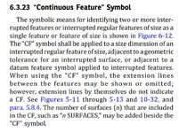
"The number of surfaces "n" that are included in the CF, such as “n SURFACES,” may be added beside the “CF” symbol."

or you would NOT use 8x for position (but still keep 8x for size Ø.500±.015)
 
So, you don't care what your suppliers can do and the suppliers don't care about your product? You have worse problems than feature control frames. If they are vastly opposed to one another they will interpret whatever you put on the drawing in vastly different ways. I say no matter the choice, they will chose to screw you over because you refuse to decide what you need and put that on the drawing and accept no-bid from the garbage suppliers.

Runout is only infeasible if there is no feature to measure against as a datum feature. If so, then as I expected, the initial image was misleading.

I'd suggest working for a company that isn't run as badly as the one you are at.

If would be up to each supplier then we will use only plus minus. No other controls. And beside of that each supplier has its own QA and their interests and vastly opposed. I have only drawing and not 5 or more -one for each supplier-

Yes, it is true. Runout is is not feasible due to the physical realities of the part.

Profile is a tool that is perceived that a CMM is needed, even this is not necessary true. But the perception is the reality.
Again, from the theory point of view what do YOU see the differences between the callouts could be? You can include profile + position, if you prefer (for my own education)
 
I'd suggest working for a company that isn't run as badly as the one you are at.

Their philosophy is rather simple: define the drawing and send it out for the quotes for multiple suppliers. Now, if we are going to ask each supplier which way they “would like to see” our drawing defined, then we will be in a never-ending cycle of permanently and constantly changing drawings. Which cycle is not feasible and economically sustainable, probably for any company, regardless of its size.

You have worse problems than feature control frames. If they are vastly opposed to one another they will interpret whatever you put on the drawing in vastly different ways.

That is exaclty what I am tryint to avoid. I want a clear interpretation of the callouts.
Back to the drawing: which is that clear interpretation? which option would you think won't have issues of be interpreted in different ways?
 
You have a unique, to you, problem. This one time you can ask your suppliers what they will do. It takes a few minutes to make an email and send it.

I am not the one at your supplier making the interpretation. If you want clarity - you have to ask them. They can and possibly will interpret it as anything from what you want to what you don't want to simply ignoring it the way they ignore profile tolerances.
 
Last edited:
Burunduk,
So in your opinion, you would use 8x size (Ø.500±.015) and 8x position AND CF symbol? I am thinking that because of what you posted
"The number of surfaces "n" that are included in the CF, such as “n SURFACES,” may be added beside the “CF” symbol."

or you would NOT use 8x for position (but still keep 8x for size Ø.500±.015)
Personally, if the best choice functionally is plus and minus size and a tolerance of position, I would place the CF symbol near the size dimension. Logically, that symbol would also apply to the position feature control frame associated with the size dimension, meaning that if the size is of a continuous feature, the controlled axis should also be derived from a single continuous feature. Although it's allowed, when I use CF, I avoid specifying the number of places (nX) as I think it's redundant most of the time. I prefer "This interrupted feature is to be treated as a single continuous feature" over "These 8 features are to be treated as a single continuous feature".
 
Burunduk,

If the size is to be controlled then why not use a classical profile and position and forget entirely about CF with position?
It is a known figure in the standard (profile to control de size and form; position to control de location/orientation).
And if you want you can use CF with profile (another known figure in the standard)
For some reason I am against the CF used with position. Does not sit well with me.
I think it is not clear hence the standard does not show it.
 

Part and Inventory Search

Sponsor