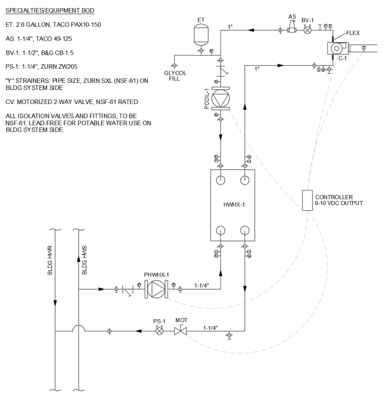
Sorry all, not ignoring you, just had to meet a deadline on another project. Here is the full diagram. This is a case of a PM telling me, "I already ordered the equipment and some of it is on site; can you just draw up a diagram to make sure I didn't miss anything?". Basically the pumps and heat exchanger are already on site so I'm trying to make things work, if possible. I'm currently trying to get some more information but just to answer some questions:
Pressures: trying to get that information but it's likely around 30 psi +/- 10 psi. I agree that it would be good to just connect it directly without a pump but then we would have to buy proportional control valves since we need to dial in the temperature. So I'm trying to make the pumps work if possible, which will be controlled with a 0-10 VDC input.
Why the pump is variable speed: see diagram, we're trying to maintain a 70 °F discharge air temperature from outdoor air that varies throughout the year between -10 and 100 °F.
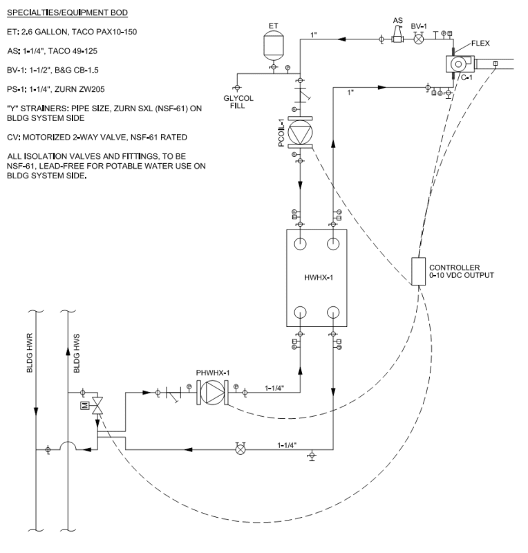
Sorry for the control valve symbol confusion, wasn't quite sure how to show it.
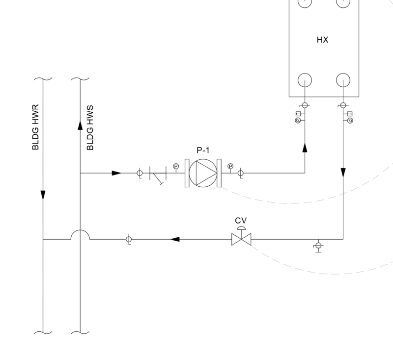
"CV" (now "MOT") is on/off, yes. Loop pressures could fluctuate slightly, yes. But I believe the BLDG main pumps are set up to maintain constant pressure. HX flow to vary to maintain discharge air temperature.
S/R temps for bldg mains: 140/120. Flow will vary, there are 6 different locations across the building where this setup with occur. 9 pumps, each slightly different flow but all around 20-30 gpm. fan coil side of HX, looking for 138 supply and 108 return.