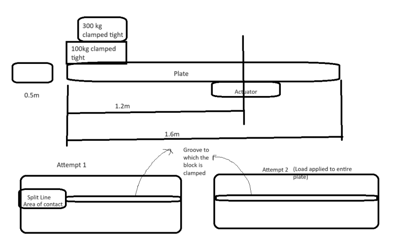
I am currently running a FEA analysis on a plate for my project where a block is clamped to one of the free ends of a 100mm thick plate. How do I model the clamping effect accurately in SolidWorks FEA?
I made a few attempts -
Attempt 1
I modeled the block as a remote mass and gave it higher CG in Y axis (straight up). For area of contact I made a split line area and connected that remote mass to the area and applied gravity, it gave me a max deflection of 60 microns.
Attempt 2 -
I made same set up but did not use split line area instead I connected the remote mass to the entire of area of plate (the top face)
I have attached a picture for reference with front and top views (bottom two views next to each other)
Thank you for taking the time out of your day to read this post.

