×
INTELLIGENT WORK FORUMS
FOR ENGINEERING PROFESSIONALS

Contact US

Log In

Come Join Us!

Are you an
Engineering professional?
Join Eng-Tips Forums!
  • Talk With Other Members
  • Be Notified Of Responses
    To Your Posts
  • Keyword Search
  • One-Click Access To Your
    Favorite Forums
  • Automated Signatures
    On Your Posts
  • Best Of All, It's Free!

*Eng-Tips's functionality depends on members receiving e-mail. By joining you are opting in to receive e-mail.

Posting Guidelines

Promoting, selling, recruiting, coursework and thesis posting is forbidden.

Students Click Here

"U" bolt Anchor in Concrete

"U" bolt Anchor in Concrete

"U" bolt Anchor in Concrete

(OP)
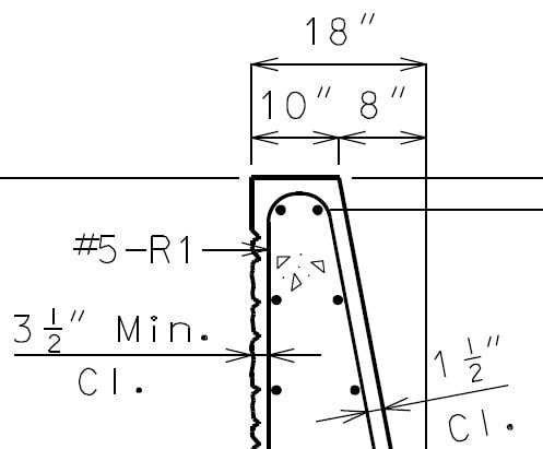
I am analyzing the anchors for an AASHTO pedestrian fence according to the following detail. This configuration was provided to me and I typically use an alternate anchoring detail. However, for this project, the detail was specified by another engineer and I am tasked with checking it. I have reviewed the ACI 318 but have found little direct information about this configuration.


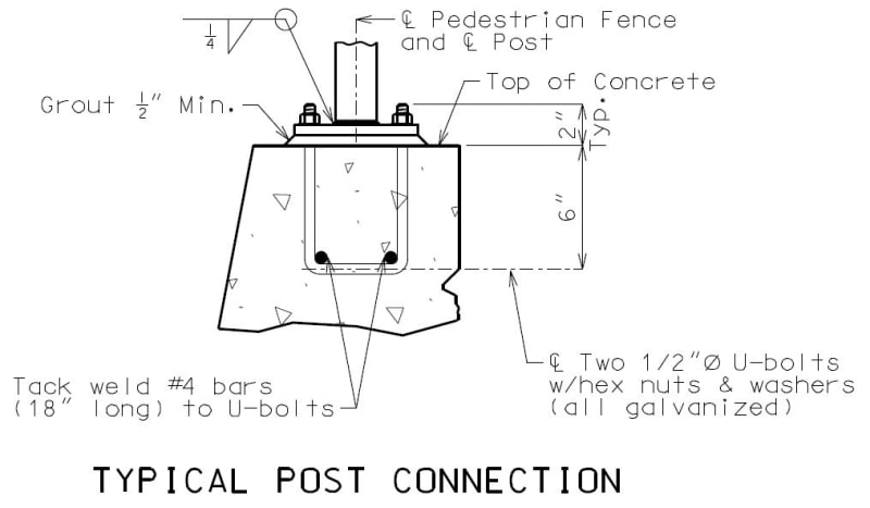
The fence is mounted to this concrete barrier:


My question is: How should this be analyzed? Do the "U" bolts get checked for development? Or do I use the anchoring to concrete provisions with some sort of modification?

Thanks for any help!

RE: "U" bolt Anchor in Concrete

One approach might be to treat the U-bolts as two separate J-bolts. I'm sure that the U-bolt configuration has more capacity than this method will indicate but I don't know of a way to demonstrate that additional capacity.

RE: "U" bolt Anchor in Concrete

Tack welding galvanized "U" to the rebar?
That sounds a bit iffy.

= = = = = = = = = = = = = = = = = = = =
P.E. Metallurgy, consulting work welcomed

RE: "U" bolt Anchor in Concrete

With that detailing, this isn't going to be a pullout mechanism so I'm less concerned about whether it's a J-bolt or something like that. I'd likely start by just looking at the concrete breakout modes and see whether it works. If it does, I'd play around with the rest of the mechanisms to make sure there isn't a real problem, but wouldn't be all that concerned. You can do some breakout capacity increases based on it being a moment loading on the bolt group, as well.

I agree that the welding of the rebar is a bit weird, but I'd consider that just a fitup helper so they are one unit for placement. They've basically set the dimensions as a template with the rebar being welded like that and the use of the u-bolts.

RE: "U" bolt Anchor in Concrete

Go through all that trouble to get a fancy custom galv U-bolt....then lets grind off the galv and weld a black bar to it.

Why not just use wire tires. Cut plywood templates of the post holes to hold the tops during casting.

RE: "U" bolt Anchor in Concrete

By welding the bars to it you have a rigid cage which can be tied more easily. The black bar is embedded below the corrosion zone.

RE: "U" bolt Anchor in Concrete

I would superimpose the U-bolts and the #4 x 18" bars (to scale and in position) on the barrier section. Then you'll be able to see whether the U-bolt will fit between the longitudinal bars in the top of the barrier, and assuming they do fit, I think you'll be able to tell that the U-bolts will be anchored into the barrier such that the capacity is controlled by the tensile strength of the #5 stirrups/ties in the barrier.

RE: "U" bolt Anchor in Concrete

Why wouldn't you weld the #4 to the U-bolt, then HDG the assembly?

-----*****-----
So strange to see the singularity approaching while the entire planet is rapidly turning into a hellscape. -John Coates

-Dik

RE: "U" bolt Anchor in Concrete

Quote:

Why wouldn't you weld the #4 to the U-bolt, then HDG the assembly?

Because it's a waste of galvanizing. Only the exposed portions of the u-bolts, and maybe an inch or so of the embedded portions, need protection.

RE: "U" bolt Anchor in Concrete

I would think the galvanizing would be useful in the concrete, if it cracks, water gets in, it would offer protection, isnt galvanized similar to epoxy coated for protection?

RE: "U" bolt Anchor in Concrete

Galvanizing is more robust. Even if you have small areas without coating the remaining zinc will act sacrificially and still provide a degree of corrosion protection to the uncoated area.

RE: "U" bolt Anchor in Concrete

That looks like a detail from a highway department standard detail.

If in USA, then what state are you in?

Every now and then we have to do a manual back check of a TxDOT standard detail......and they all fail miserably.

RE: "U" bolt Anchor in Concrete

Quote (JoelTXCive)

Every now and then we have to do a manual back check of a TxDOT standard detail......and they all fail miserably.

What type of details are you checking?

RE: "U" bolt Anchor in Concrete

@Bridgesmith - I deal mostly with the TxDOT headwalls, wingwalls & retaining walls.

The TxDOT retaining wall standards are pretty scary if you put them into retaining wall software. The new standards are better than the old ones, but in my experience, they all slide or have other issues with the footings in the software.

The TxDOT headwall standard will let you go 16ft tall with an 8" wall. A guy in our office built a Staad model with their geometry and loading assumptions. He couldn't get it to work.

RE: "U" bolt Anchor in Concrete

But does Texas have problems with performance of headwalls?

RE: "U" bolt Anchor in Concrete

Interesting, Joel. I thought maybe you were checking the bridge railing, which, like ours, fails miserably 'by the numbers', but held up fine in the full-scale crash testing.

RE: "U" bolt Anchor in Concrete

Hokie - No, I would say Texas does not have problems with headwalls. I'm aware of a couple problems with cantilevered walls, but for the volume of these walls that are installed each year; I would still say the walls are good.

I think they are empirically good walls, and am comfortable using them on most jobs. On TxDOT specific jobs, there really isn't any decision to be made since the state is only going to build one of their standard walls. And there is plenty of money available to change out the back fill if needed.

RE: "U" bolt Anchor in Concrete

All DOT railings in my area (pedestrian or highway traffic) are standard dwgs from the DOT. We only design the anchorage to the deck.

RE: "U" bolt Anchor in Concrete

Our old railings and our new (MASH) railings utilize the crash tested configuration for everything, including the anchorage and deck reinforcing, because none of it is adequate per analysis.

Anyway, back to the subject.

BS2, have you superimposed the fence anchorage on the barrier with the reinforcing, with everything drawn to scale (including bend radii) to see if/how everything fits? If my assumptions about the U-bolt dimensions are correct, the analysis may be very much simplified. Read on.

If the continuous longitudinal bars in the top of the barrier are going to have to go through the U-bolts, then breakout of the U-bolts is pretty much impossible, and the tensile strength of the U-bolt is the limiting capacity. I would say the same would be true if at least a couple of the #5 stirrups/ties encompass the #4 by 18" bars that go through the U-bolts.

RE: "U" bolt Anchor in Concrete

Quote (BridgeSmith)

Because it's a waste of galvanizing. Only the exposed portions of the u-bolts, and maybe an inch or so of the embedded portions, need protection.

I'm not sure I follow. Corrosion is a massive issue with reinforced concrete. So much so that many DOTs in salt regions are going to 100% galvanized rebar in all parts of their bridges. Galvanizing anchors is hardly unprecedented or even unusual. I would do exactly what dik said; fabricate the u-bolt/rebar assembly first and then dip the whole thing.

RE: "U" bolt Anchor in Concrete

Nothing wrong with either of those approaches, except for transportability of the previously welded assembly.

RE: "U" bolt Anchor in Concrete

Quote (Enginerdad)

Corrosion is a massive issue with reinforced concrete. So much so that many DOTs in salt regions are going to 100% galvanized rebar in all parts of their bridges.

Well, the bridge deck is a whole different beast than a fence anchorage on top of a barrier. Plus, the rebar and bottom corners of the U-bolts, where the galvanizing would be removed to tack weld the rebar, are embedded 5"+ into the concrete, while the top layer of deck reinforcing has typically only 2" to 2-1/2" of cover.

I also don't know of any DOTs that are using galvanized rebar in their substructures.

RE: "U" bolt Anchor in Concrete

(OP)

Quote (JoelTXCive)

That looks like a detail from a highway department standard detail.

If in USA, then what state are you in?

Yes, it is for a Missouri DOT project.

Quote (BridgeSmith)

BS2, have you superimposed the fence anchorage on the barrier with the reinforcing, with everything drawn to scale (including bend radii) to see if/how everything fits? If my assumptions about the U-bolt dimensions are correct, the analysis may be very much simplified. Read on.

If the continuous longitudinal bars in the top of the barrier are going to have to go through the U-bolts, then breakout of the U-bolts is pretty much impossible, and the tensile strength of the U-bolt is the limiting capacity. I would say the same would be true if at least a couple of the #5 stirrups/ties encompass the #4 by 18" bars that go through the U-bolts.

Here is the overlayed detail:


It looks like one of the longitudinal bars will go through the U-bolts. And the #5 stirrups are at 12"oc so the #4 by 18" bars should be encompassed by at least one stirrup.

Thanks for the help!

RE: "U" bolt Anchor in Concrete

It's going to be hard to get those U-bolts in there with the #4 bars welded to them, unless they're placed before that longitudinal bar in the barrier that goes through the U-bolts.

As far as anchorage, I think you're pretty well set, with a continuous bar through the U-bolts, and a stirrup or 2 around the #4. It might be a little better to move the one #4 so they're both inside the stirrups.

Red Flag This Post

Please let us know here why this post is inappropriate. Reasons such as off-topic, duplicates, flames, illegal, vulgar, or students posting their homework.

Red Flag Submitted

Thank you for helping keep Eng-Tips Forums free from inappropriate posts.
The Eng-Tips staff will check this out and take appropriate action.

Reply To This Thread

Posting in the Eng-Tips forums is a member-only feature.

Click Here to join Eng-Tips and talk with other members! Already a Member? Login


Resources

Low-Volume Rapid Injection Molding With 3D Printed Molds
Learn methods and guidelines for using stereolithography (SLA) 3D printed molds in the injection molding process to lower costs and lead time. Discover how this hybrid manufacturing process enables on-demand mold fabrication to quickly produce small batches of thermoplastic parts. Download Now
Design for Additive Manufacturing (DfAM)
Examine how the principles of DfAM upend many of the long-standing rules around manufacturability - allowing engineers and designers to place a part’s function at the center of their design considerations. Download Now
Taking Control of Engineering Documents
This ebook covers tips for creating and managing workflows, security best practices and protection of intellectual property, Cloud vs. on-premise software solutions, CAD file management, compliance, and more. Download Now

Close Box

Join Eng-Tips® Today!

Join your peers on the Internet's largest technical engineering professional community.
It's easy to join and it's free.

Here's Why Members Love Eng-Tips Forums:

Register now while it's still free!

Already a member? Close this window and log in.

Join Us             Close