Hello Guys,
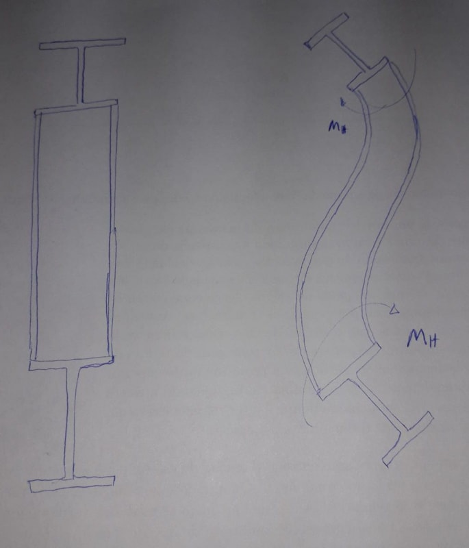
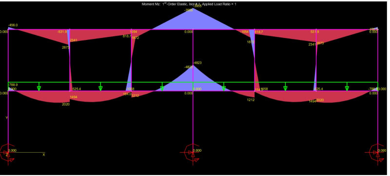
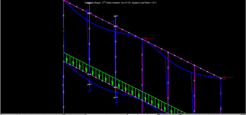
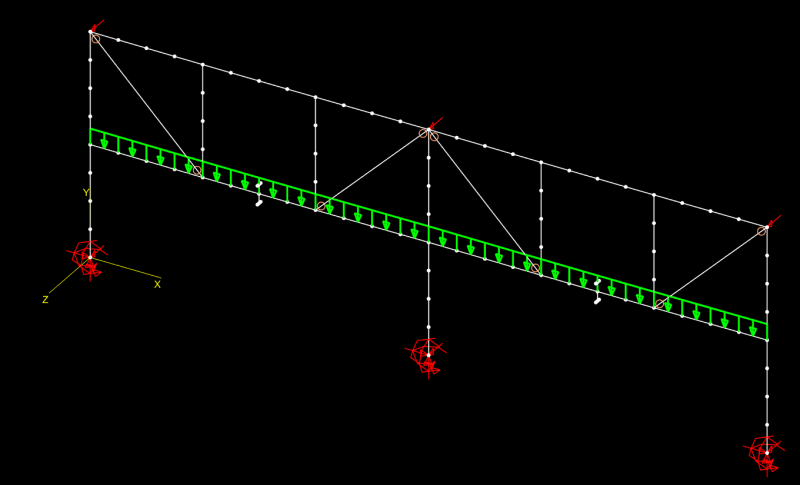
I have the following frame( Showing only the necessary part of the structure for the understanding of the problem). The Span is 9,00m(30ft) and the intermediate beam is suporting non-structural masonry. In order to increase the stiffness of the frame, share a part of the load of the intermediate to the top beam and give better suport to the masonry wall, i introduced the green ties. My question is, if i utilize rigid connections, the ties will brace the beams for LTB(Torsional bracing)?
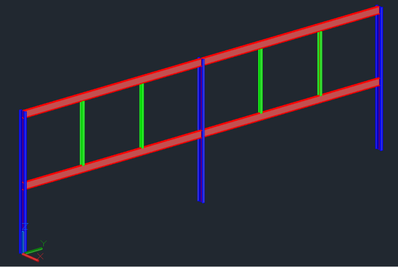
Is there a document that deals with this kind of bracing?
I don't think that it won't be as effective as a traditional bracing where the beams are on the same horizontal plane but may be sufficiente.
Thanks in advance.
I have the following frame( Showing only the necessary part of the structure for the understanding of the problem). The Span is 9,00m(30ft) and the intermediate beam is suporting non-structural masonry. In order to increase the stiffness of the frame, share a part of the load of the intermediate to the top beam and give better suport to the masonry wall, i introduced the green ties. My question is, if i utilize rigid connections, the ties will brace the beams for LTB(Torsional bracing)?
Is there a document that deals with this kind of bracing?
I don't think that it won't be as effective as a traditional bracing where the beams are on the same horizontal plane but may be sufficiente.
Thanks in advance.