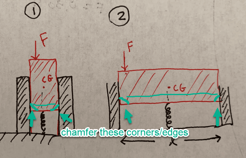
Let's say i'm designing a rectangular button with these two different cross sections. The button is constrained on the left and right by a vertical wall and supported on the bottom by a spring directly below the CG. The only difference between options 1 and 2 is length l.
Three questions:
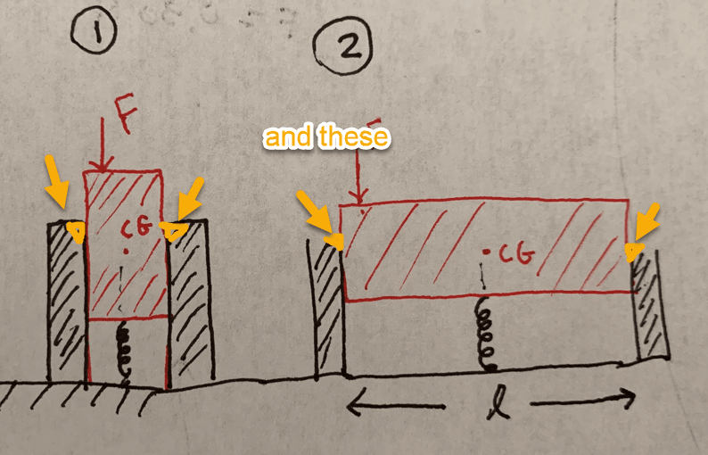
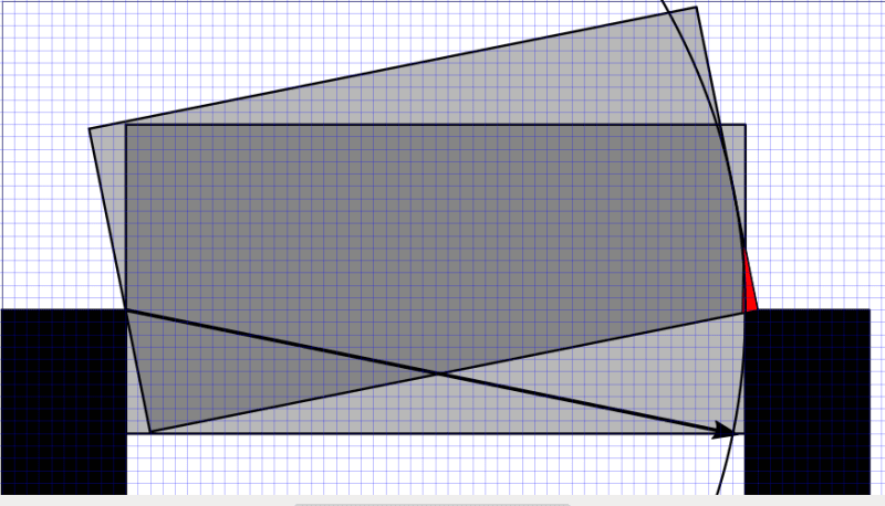
1. If a force is applied off center, why is option 2 more prone to "jamming"?
2. Why can be done geometrically to reduce likelihood of jamming?
3. What if the button was a cylinder instead of a rectangle, would that help and if so, why?
[URL unfurl="true"]https://res.cloudinary.com/engineering-com/image/upload/v1652147076/tips/IMG_2919_brvepq.heic[/url]
Three questions:
1. If a force is applied off center, why is option 2 more prone to "jamming"?
2. Why can be done geometrically to reduce likelihood of jamming?
3. What if the button was a cylinder instead of a rectangle, would that help and if so, why?
[URL unfurl="true"]https://res.cloudinary.com/engineering-com/image/upload/v1652147076/tips/IMG_2919_brvepq.heic[/url]
![[bat]](/data/assets/smilies/bat.gif "[bat] [bat]")