AutoDesign123
Automotive
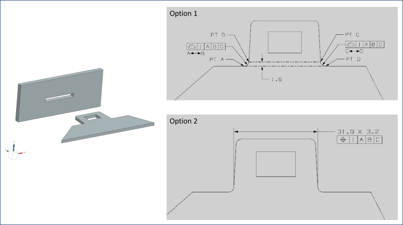
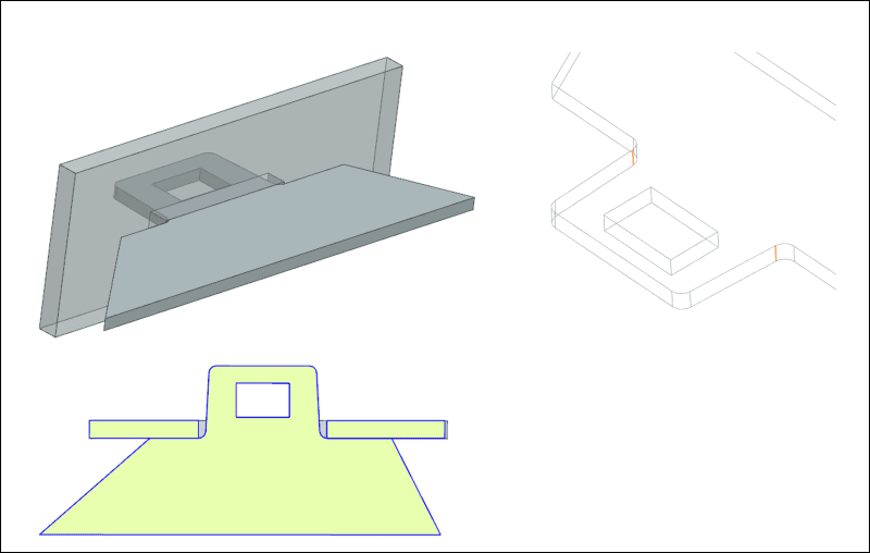
I have a part that contains a number of tabs with slots around the perimeter of the part.
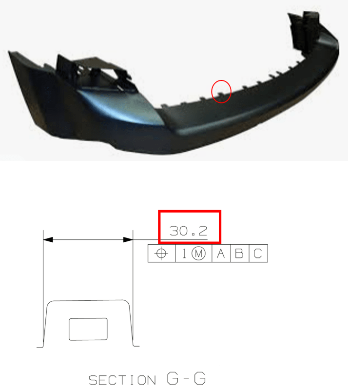
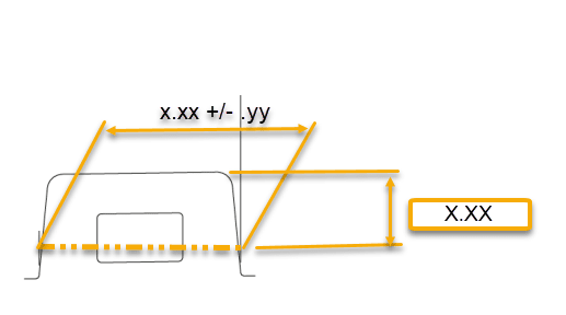
I would like to verify the position and width at the base of each slot. The challenge that I'm struggling to address is that the width at the base (red box) differs slightly for each slot. I'd like to avoid creating a drawing view for each individual tab slot and was wondering if there was something I could do that communicated that I would like the base width of each slot checked based on the model.
I've considered calling out a surface profile on both sidewalls and creating a single section view with a note below saying "TYPICAL 20 PLACES MARKED X" but that would check the entire length of the sidewall and I'm only interested in the width.
Would anyone have anything that I could do that I haven't considered?