Continue to Site

Eng-Tips is the largest engineering community on the Internet

Intelligent Work Forums for Engineering Professionals

  • Congratulations waross on being selected by the Eng-Tips community for having the most helpful posts in the forums last week. Way to Go!

GD&T - Same Callout Applied to Many Dimensions

Status
Not open for further replies.

AutoDesign123

Automotive
Apr 21, 2022
3
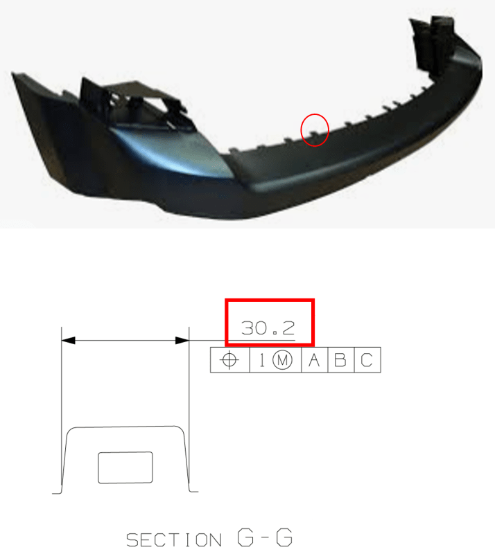
I have a part that contains a number of tabs with slots around the perimeter of the part.
Example_xsde0r.png


I would like to verify the position and width at the base of each slot. The challenge that I'm struggling to address is that the width at the base (red box) differs slightly for each slot. I'd like to avoid creating a drawing view for each individual tab slot and was wondering if there was something I could do that communicated that I would like the base width of each slot checked based on the model.

I've considered calling out a surface profile on both sidewalls and creating a single section view with a note below saying "TYPICAL 20 PLACES MARKED X" but that would check the entire length of the sidewall and I'm only interested in the width.

Would anyone have anything that I could do that I haven't considered?
 
Replies continue below

Recommended for you

Not quite getting how one applies a position to a width of a non-FOS. Seems like more of a profile thing.
 
TheTick and ctopher,

If he applies a tolerance to the width, it becomes a feature of size.

The width should be something like 20[×]30.2[±]0.2. If the size tolerance is is critical and tight, the problem is solved. If the width is sloppy and not critical, then profile is the right way.

--
JHG
 
Hi, JHG

From the drawing, this dimension 30.2 is applied to virtual sharps. I don't think this is a feature of size.

Best regards,

Alex
 
That internal square hole looks like a FOS. Since it likely engages a snap. it seems more relevant, as well.

Proposal:
Use position for the hole. Control outer profile relative to each respective hole.
 
AutoDesign123,

Do you have a view in which you could label the tabs with numbers? If yes, you could change the 30.2 to a letter, say D, and then tabulate the widths to show them as D-1, D-2, D-3, etc. You could do the same thing with slot dimensions if they also vary.
 
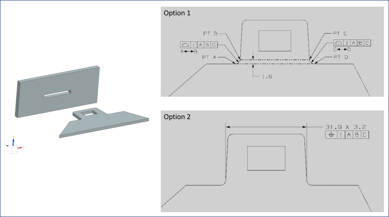
Thanks everyone for your responses. I've added an image to show everyone a bit more detail what I'm hoping to check. I need to make sure that the tab needs fits into the slot and there are 18 of these tabs of varying widths (31.9mm dimension in my example - Option 2). I've included what I believe are two options based on the discussion.

Option 1:
- use a surface profile between two points on both sidewalls of the tab feature
- would it be acceptable to use a view that shows all tabs and indicate each one with a note "TAB X". Then create a detail view of one tab and use this notation to express that the requirement applies to "ALL TABS LABELLED TAB X"?

Option 2:
- updated the callout to include the material thickness which makes it a FOS and appropriate to use the positional callout.
- negative of this approach is that I would need to dimension each tab feature
- the suggestion provided by pmarc (label the dimension with a letter and create a table) is great and would only require me to make one view

Anything that I've missed or that's wrong with either option?

Example2_csmi5j.png
 
No. Neither option is good.

A better approach is the one TheTick proposed. Use position for the hole. Control outer profile relative to each respective hole.

Why do you want to control the minor fillets? There is no mating features that come into contact with the fillets.

Dimension 31.8 is not clearly defined. It is also not a feature of size.

Tab location is "largely" defined by the sides of tabs rather the fillets.

Best regards,

Alex

 
jassco said:
Why do you want to control the minor fillets? There is no mating features that come into contact with the fillets.

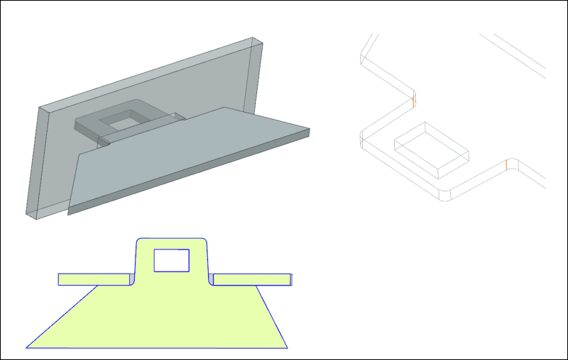
The sidewalls of the tab at its base (including fillets) define the position (left/right) of the tab in the mating feature (see image below). The hole engages with a snap but that snap does not dictate left/right position of the tab.
Example4_y3xchv.png


jassco said:
A better approach is the one TheTick proposed. Use position for the hole. Control outer profile relative to each respective hole.
I'm struggling in understanding how to implement this. I understand that I can define the position of the hole relative to the datums. To "control outer profile relative to each hole" means to me that I would need to create new datums using the hole and then use surface profile to control the tab walls back to the datums created by the hole?

jassco said:
Dimension 31.8 is not clearly defined. It is also not a feature of size.
This has been mentioned lots so I did some reading of ASME Y14.5 to try and improve my understanding.

ASME Y14.5 - 3.35.2 Regular Feature Of Size said:
"...one cylindrical surface, a spherical surface, a circular element, or a set of two opposed parallel line elements or opposed parallel surfaces associated with a single directly toleranced dimension"
In the image above, the wireframe view shows the two lines in orange that I've dimensioned. These lines are parallel ["two opposed parallel line elements"]. The tolerance isn't in the dimension directly but is covered by a default tolerance from my title block. If you exclude the lack of a direct tolerance can you help me understand why this would not be considered a regular feature of size?
 
autodesign

why is the tab tapered?

combine option one and two and use gage points mid point of the tabs to measure the width. also the angle of each side will have to be specified. then use a true position or profile of surface. way easier then measuring a theoretical internal sharp corners.
to measure gage points a cmm will be required. but the tolerance should be liberal. eg you could make d view and e view
 
AutoDesign,
In your first image, there is an MMC modifier that follows the position tolerance value. It would actually make sense to apply it at the base of the tab so that the width includes the entire feature that is being engaged with the slot - including the two radii (according to the assembly depiction image you posted later down the thread). Then theoretically it is possible to inspect using a hard gage made as your worst case mating part. Easier and functionally more appropriate than having to engage the top tangency lines between the angled surfaces and the radii (the ones you've shown in orange).
 
Root corners are NOT FOS. Maybe... under the most extreme definition of the term, but not under the common competent understanding of GD&T.

Chasing down root corners that intersect an organic surface is a fool's errand. Ditto for measuring off a tangency.

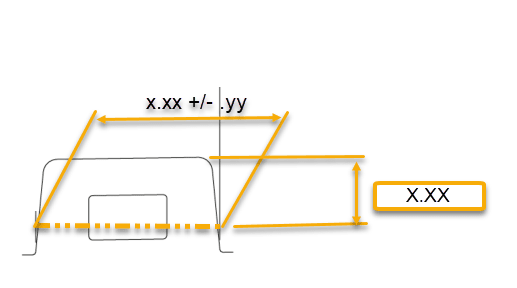
In cases where I can not measure a boss diameter or width at the end, I specify a basic distance from the end and measure at the section. CMMs can do this no problem. Also gage-friendly and repeatable.
OFFSET_WIDTH_tnn411.png
 
Status
Not open for further replies.

Part and Inventory Search

Sponsor