Francesco Bro
Aerospace
- Jan 31, 2021
- 24
Hi,
I have been reading simple example problems of FEM vs analytical solutions, and I run into a very simple (and maybe stupid) doubt which answer I couldn't find over days after searching in FEM textbooks!
Let's assume we have a classical cantilever Euler-Bernoulli beam, clamped at the root and free at the tip. We know the classical governing equation for this problem according to Strength of Materials is a 4th order differential equation: EI d^4(v(x))/dx^4 - q(x) = 0
If there is no distributed load, the solution of the displacements in the interior of the beam will be a 3th order polynomial. Furthermore, if we want to solve it adopting a classical 1-FEM-element composed of 2 nodes, in which Hermite Polynomials are formulated and a cubic polynomial is defined for the displacements function v(x) (4 parameters to get constrains of vertical displacements and rotations), the FEM will lead to the exact solution. Both v(x)_FEM v(x)_exact will match.
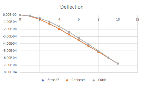
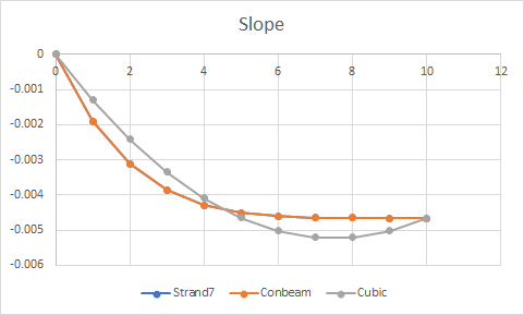
However, if the distributed load is constant, linear, quadratic, and so on... and if we want to solve it adopting a classical 1-FEM-element with 2 nodes, the displacements at the interior of the element v(x)_FEM will no longer match the analytical solution v(x)_exact.
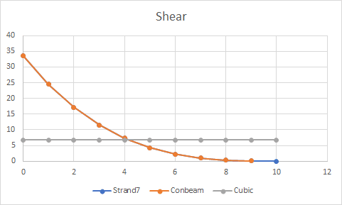
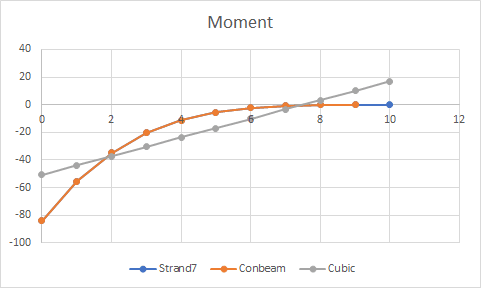
For instance, assuming a distributed load q(x) of quadratic form, the analytical solution of v(x)_exact will be a 6th order polynomial, against the same cubic Hermite polynomials for v(x)_FEM. Obviously, there will be an error on the solution, and even worse for forces, moments, stresses, strains since the errors will magnify when differentiating from v(x). However... the displacements computed at the tip node will still match between 1-FEM-element and the analytical solution!
Why is this happening? What am I missing? Is it related to the weak form formulation of the Finite Element Method and the essential/natural BCs?
Thanks.
Francesco
I have been reading simple example problems of FEM vs analytical solutions, and I run into a very simple (and maybe stupid) doubt which answer I couldn't find over days after searching in FEM textbooks!
Let's assume we have a classical cantilever Euler-Bernoulli beam, clamped at the root and free at the tip. We know the classical governing equation for this problem according to Strength of Materials is a 4th order differential equation: EI d^4(v(x))/dx^4 - q(x) = 0
If there is no distributed load, the solution of the displacements in the interior of the beam will be a 3th order polynomial. Furthermore, if we want to solve it adopting a classical 1-FEM-element composed of 2 nodes, in which Hermite Polynomials are formulated and a cubic polynomial is defined for the displacements function v(x) (4 parameters to get constrains of vertical displacements and rotations), the FEM will lead to the exact solution. Both v(x)_FEM v(x)_exact will match.
However, if the distributed load is constant, linear, quadratic, and so on... and if we want to solve it adopting a classical 1-FEM-element with 2 nodes, the displacements at the interior of the element v(x)_FEM will no longer match the analytical solution v(x)_exact.
For instance, assuming a distributed load q(x) of quadratic form, the analytical solution of v(x)_exact will be a 6th order polynomial, against the same cubic Hermite polynomials for v(x)_FEM. Obviously, there will be an error on the solution, and even worse for forces, moments, stresses, strains since the errors will magnify when differentiating from v(x). However... the displacements computed at the tip node will still match between 1-FEM-element and the analytical solution!
Why is this happening? What am I missing? Is it related to the weak form formulation of the Finite Element Method and the essential/natural BCs?
Thanks.
Francesco
")