Tek-Tips is the largest IT community on the Internet today!
Members share and learn making Tek-Tips Forums the best source of peer-reviewed technical information on the Internet!
-
Congratulations TugboatEng on being selected by the Eng-Tips community for having the most helpful posts in the forums last week. Way to Go!
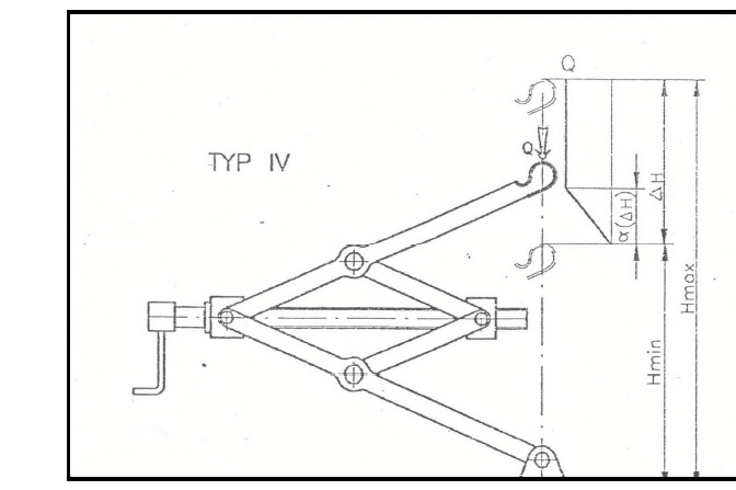
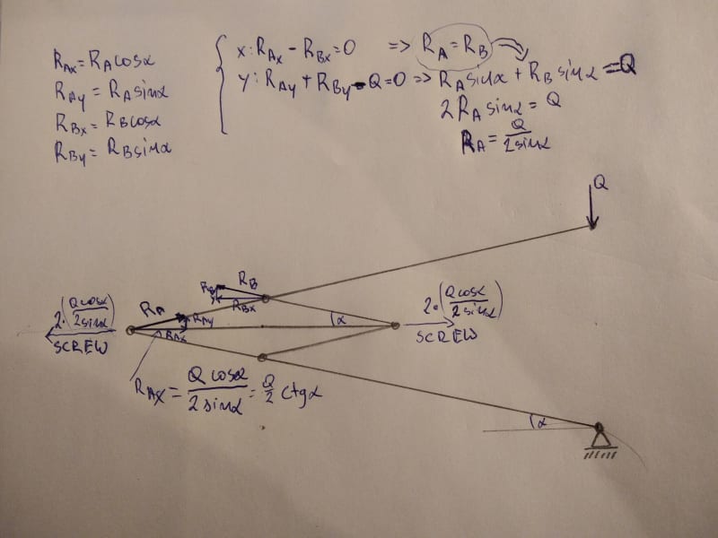
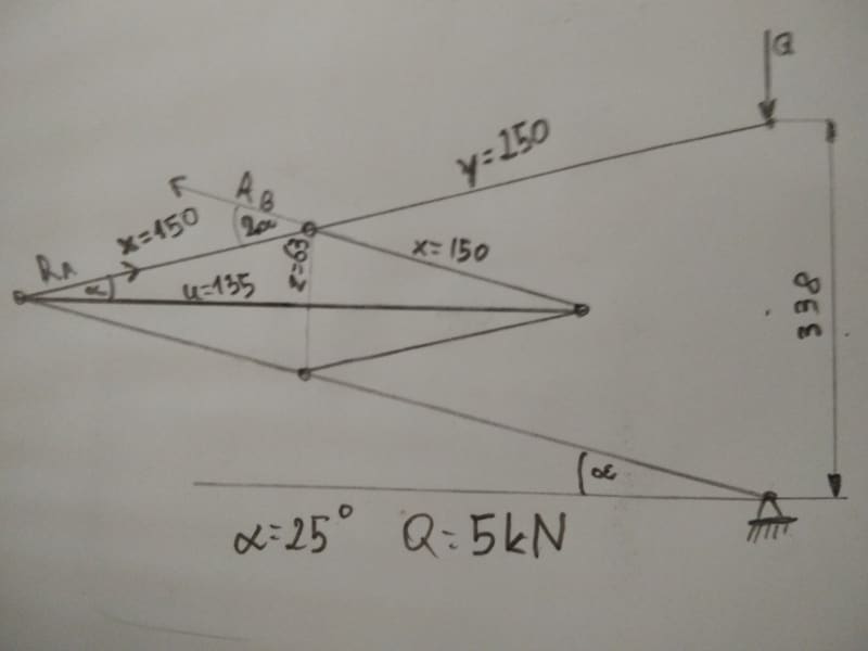
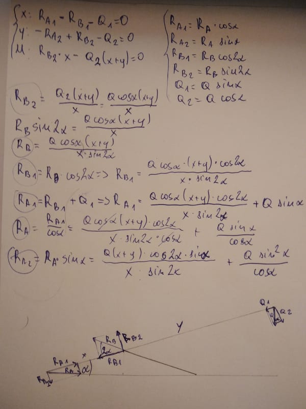
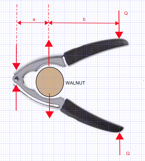
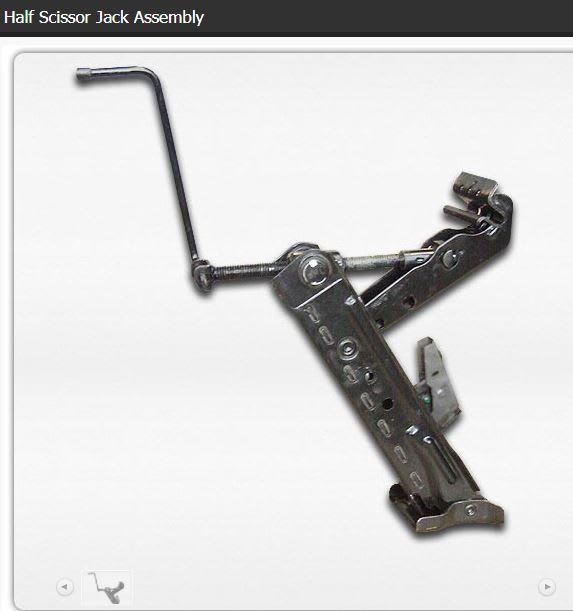
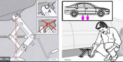
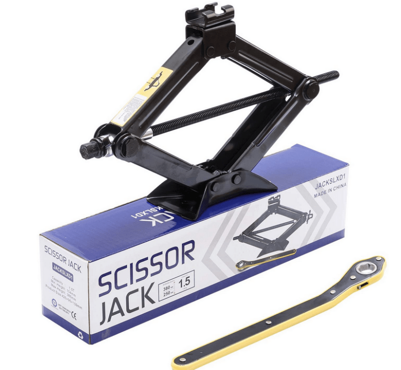
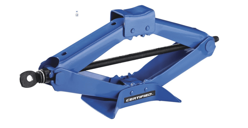
Forces in scissar lift
- Thread starter Agunia
- Start date

Similar threads
- Question
- Question