sticksandtriangles
Structural
- Apr 7, 2015
- 499
I am struggling to understand double sided diaphragm connections and was looking for some guidance.
Please reference the images below.
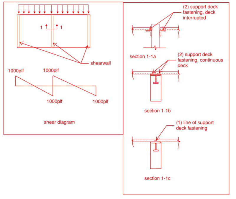
Consider this as a flexible diaphragm with a full length shearwall.
Let's also assume that my diaphragm capacity is 1000plf based on a certain deck attachment pattern.
Do you consider section 1-1a and 1-1b to be identical in terms of capacity? I am thinking in terms of:
1) diaphragm shear capacity
2) in terms of ability to deliver force down to the shear wall below.
My intuition tells me something is inherently different between section 1-1a and 1-1b, but I cannot put my finger on it.
My gut tells me that 1-1a and 1-1b has that same ability to resist diaphragm shear, but section 1-1b has less capacity to deliver force to the shear wall below? Then devil's advocate in me tells me how is section 1-1b any different than if they just chopped the deck in half over the shearwall?
The way I see it, Section 1-1a diaphragm shear capacity = 1000plf, section 1-1a capacity to deliver force to shearwall below = 2*1000plf
Do you see any difference between 1-1a and 1-1b in terms items 1 or 2 listed above?
Section 1-1c is what I typically see and I consider diaphragm shear capacity and ability to deliver force down the shearwall below the same (1000plf). In this case, section 1-1c would be inadequate to transfer the total 2000plf demand down to the shearwall below (total jump in the shear force diagram).
Thanks for your thoughts.
S&T
Please reference the images below.
Consider this as a flexible diaphragm with a full length shearwall.
Let's also assume that my diaphragm capacity is 1000plf based on a certain deck attachment pattern.
Do you consider section 1-1a and 1-1b to be identical in terms of capacity? I am thinking in terms of:
1) diaphragm shear capacity
2) in terms of ability to deliver force down to the shear wall below.
My intuition tells me something is inherently different between section 1-1a and 1-1b, but I cannot put my finger on it.
My gut tells me that 1-1a and 1-1b has that same ability to resist diaphragm shear, but section 1-1b has less capacity to deliver force to the shear wall below? Then devil's advocate in me tells me how is section 1-1b any different than if they just chopped the deck in half over the shearwall?
The way I see it, Section 1-1a diaphragm shear capacity = 1000plf, section 1-1a capacity to deliver force to shearwall below = 2*1000plf
Do you see any difference between 1-1a and 1-1b in terms items 1 or 2 listed above?
Section 1-1c is what I typically see and I consider diaphragm shear capacity and ability to deliver force down the shearwall below the same (1000plf). In this case, section 1-1c would be inadequate to transfer the total 2000plf demand down to the shearwall below (total jump in the shear force diagram).
Thanks for your thoughts.
S&T