Miami Pedestrian Bridge, Part V
(OP)
This continues the discussion from Part I, II, III, and IV. Please read the other threads first:
Part I
thread815-436595: Miami Pedestrian Bridge, Part I
Part II
thread815-436699: Miami Pedestrian Bridge, Part II
Part III
thread815-436802: Miami Pedestrian Bridge, Part III
Part IV
thread815-436924: Miami Pedestrian Bridge, Part IV
Part I
thread815-436595: Miami Pedestrian Bridge, Part I
Part II
thread815-436699: Miami Pedestrian Bridge, Part II
Part III
thread815-436802: Miami Pedestrian Bridge, Part III
Part IV
thread815-436924: Miami Pedestrian Bridge, Part IV
RE: Miami Pedestrian Bridge, Part V
It was very tempting early on to see the tensioning gun and the tendon snapping as the "smoking gun", but a lot of people now don't think this is credible.
1) the crew were an experienced crew
2) you would need to pull it a considerable amount before it got to UTS
3) the rod should have been seeing less tension than it did when it was installed
4) the Collapse and separation of the deck and tendon from member 11 means it ended up in a shorter distance under the deck and hence stuck out the top end.
Remember - More details = better answers
Also: If you get a response it's polite to respond to it.
RE: Miami Pedestrian Bridge, Part V
Unfortunately, even Scientific American missed some nuances when preparing this article.
RE: Miami Pedestrian Bridge, Part V
"Do we know when the PT cables in the bottom deck/chord were stressed? Were these cables stressed after the entire truss was poured or was the bottom deck poured, then stressed, then the diagonal/verticals poured and so on?
If the cables in the bottom deck were stressed after the vertical and diagonal members and top chord were poured, this would put significant added stress to both the tension from the bottom deck trying to find its way into the node joining members 11+12 (thus magnifying the pull out failure eluded to earlier) and it would also result in some of the PT force finding its way up into member 11 as well thus further increasing the compressive demand on this member itself."
Discussed the pour and order of prestressing back in Part III at 18:00:03. Just to reiterate the structure was to be completely poured. It appears that the cold joints in the web are near the top and bottom flanges. The bottom flange was to be stressed first, if done all at once this has a significant impact on the diagonals in the web if stressing done in one step. Same between the web and canopy. Not sure if this is how it was actually done but it is most probable from their original intentions. Not sure when deck strands and canopy strands were grouted.
Obviously the prestressing if done in one step puts significant stress into the web members particularly 11 and 2 at each end. 2 appears to be beefed up compared to 11 which possibly saved it. I did horizontal and vertical shear calculations for 11 in part IV using 32.5 deg angle for 11 so these are slightly high compared to a 36 deg angle. Values are high enough to warrant a complete failure analysis of the concrete in this area due to all combined stresses. Does not appear to be enough deformed rebar to prevent failure.
There are so many ifs in this entire thing that any final conclusions are difficult. Until the NTSB releases more it only encourages more speculation.
RE: Miami Pedestrian Bridge, Part V
Remember - More details = better answers
Also: If you get a response it's polite to respond to it.
RE: Miami Pedestrian Bridge, Part V
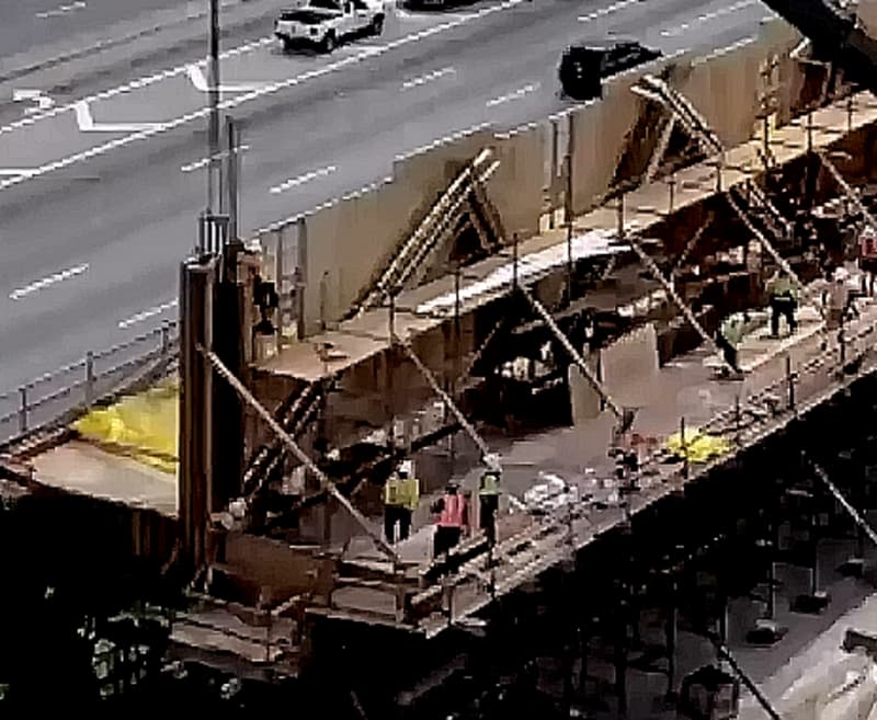
Member #3 suggests 10 bars in the standard size trusses Link
While not conclusive, it looks like the PT strands for #11 were routed left & right of #12 into the diaphragm.
RE: Miami Pedestrian Bridge, Part V
just thinking aloud because i'm not qualified to assert anything about concrete.
Happy to see questioning the sequence of tensioning.
Tensioning the deck and canopy separately i would think changes their relative lengths by elastic compression . That makes the right rectangle into a trapezoid with non=parallel ends. . How much difference is enough to put a hurt on member 12 at its bottom joint ?
Young's Modulus ?
just say 5000 psi for f'_c = 5 , using ksi
E_c = 1820 sqrt(5 ) = 4070
So, a 175 foot span might change length by 175/4070 = 0.51 inch per 1000 psi of compression ?
I don't know how to figure the bending stress at bottom of #12 from a half inch deflection at its top.. MC/I ?
Intuitively seems not much. But it's the kind of question that nags at a beginner.
Would appreciate a dismissal by anybody skilled in the craft.
old jim
Never trust a computer with anything important...
RE: Miami Pedestrian Bridge, Part V
Anyone?
RE: Miami Pedestrian Bridge, Part V
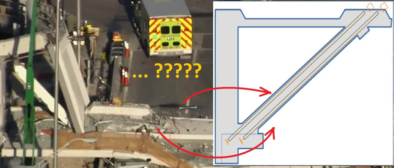
Right now I'm really more confused by this picture.
RE: Miami Pedestrian Bridge, Part V
Edit: sorry, I keep getting the compass directions reversed in my mind. I meant the to-be-constructed North span.
RE: Miami Pedestrian Bridge, Part V
At 8:53 AM, westbound travel appears to show worker on south end canopy. No "apparent" north deck blemishes or cracks---video is fuzzy somewhat.
At 9:39 AM, eastbound travel shows crane setting up, maybe the man lift basket in roadway.
www.youtube.com/watch?v=CVjBiFMXjwU
RE: Miami Pedestrian Bridge, Part V
(a) The end beam or downstand sitting on bearing : south side 3'-6" wide, north side 2'-10-1/2"
(b) First vertical member : South side No. 1 is 3'-0" wide, north 2'-10-5/8"
(c) Geometry of first diagonal Vertical:Horizontal:diagonal ratio : south side No. 2 has 1:2.14:2.37, North No. 11 has 1:1.4:1.7 approximately
(d) Axial compression of first diagonal : South No. 2 has 200kips, north side none specified.
My interpretation is a horizontal line drawn across No.2 and 11 then No. 2 has (2.37/1.7-1)*100 = 39% more horizontal shearing area than No. 11. However at a flatter slope but with the same support reaction the horizontal component or shearing force of No. 2 is (2.14/1.4-1)*100 = 53% higher than No. 11. The end result would be under identical reaction No. 2 should experience about 10% higher stress if a failure takes place on a horizontal plane.
However the axial compression is specified in No.2 and none for No.11 for the bridge being supported without free overhanging cantilever at either end during the move in the proposal drawings. So if No.11 subsequently were post-tensioned and then released/adjusted on completion then one can expect No. 2 to be similar but still has the specified 200kips left behind. When a member is compressed its shear resistance should increase. May be on balance the south side is more robust against shearing failure than the north side which collapse first.
Lastly some have raised the suspicion on the tension adjustment equipment and wonder if the members were further compressed. Two facts are relevant here:
(1) The crew was adjusting tension. It can be increasing or decreasing tension. Since No.2 and 11 are permanently under compression in service one would have thought the original tension introduced to counterbalance the overhanging cantilever action would be removed in the tension adjustment. Any suggestion of the No.11 failed by compression could be speculation unless newer information is available.
(2) It would be speculative to blame the equipment or the workmen if the crew has adjusted successfully two PT rods on the south and one in the north.
RE: Miami Pedestrian Bridge, Part V
After primary failure at base of 11, I believe there was significant secondary grinding going at base of 11 prior to bridge collapse, with vertical 12 still in place. Other members begin to fail around it--first top canopy, then finally bottom slab. When bottom slab hinges and rotates prior to being pulled off of pier, this could force top PT rod out from top canopy. Then what's left of 11-12 are thrust off slab and onto top of pier as bridge plummets to ground. Of course, this is just a theory?
[[EDIT: Scratch the rotation of bottom slab thought, as it is the bottom PT rod, not the top as I mentioned above, that extends from the anchorage blister.]]
RE: Miami Pedestrian Bridge, Part V
I do not know what your last drawing depicts either.
However it is reasonably established the top PT rod of No. 11 has been adjusted successfully. The bridge broke when the crew was adjusting the tension in the bottom PT rod because the jack was still attached to the rod after the collapse.
Where we like it or not the tension adjustment of the last PT rod, at the bottom of No.11, triggered the collapse.
I was confused by the PT tendon and PT bar so to help others I stated the following:
The deck and canopy were post-tension by PT tendon or strands, each 0.6" diameter, which are flexible and can be bent.
The truss used PT rod or bar 1-3/4" diameter which has threads and difficult to bend. The tension adjustment should be tightening or loosening the nut at the exposed end. From my experience PT bar has a nut at the concealed end too. The rod, nut and the anchor plate there are often welded together and cast in concrete to provide a locked end.
RE: Miami Pedestrian Bridge, Part V
Thanks all for response.
RE: Miami Pedestrian Bridge, Part V
The upper PT rod has stayed with memmber 11.
The lower end of the lower PT rod seems to be still attached to the deck.
This may indicate that the failure originated mostly above the deck.
Bearing in mind that the photos may be misleading.
Bill
--------------------
"Why not the best?"
Jimmy Carter
RE: Miami Pedestrian Bridge, Part V
I wouldn't lose sleep on this one.
First the canopy is post-tensioned by 62 strands but walkway deck is also post-tensioned by 214 strands so stress on No.12 is difference of the two axial shortenings.
Secondly the canopy is mainly connect to No. 12 only by its 1'-0" thickness while the bottom of No.12 is cast with a 4'-0" deep beam. If the canopy is not strong enough to pull and bend No.12, due to insufficient bonding concrete for stress transfer, then the canopy edge will adjust itself by having less than your calculated shortening or developing cracks. I would say the middle section of canopy directly above the truss is not as compressible as the rest because the truss connections. May be that is the reason the designer move the 4 set of PT tensions away from the center.
RE: Miami Pedestrian Bridge, Part V
The lump is the local thickening of concrete above each truss joint. It also serves as the tension adjustment point.
It is detail A but on top of member 10-11.
or are you talking about other bits?
A better view from the other side
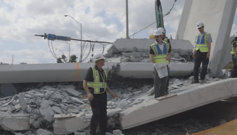
RE: Miami Pedestrian Bridge, Part V
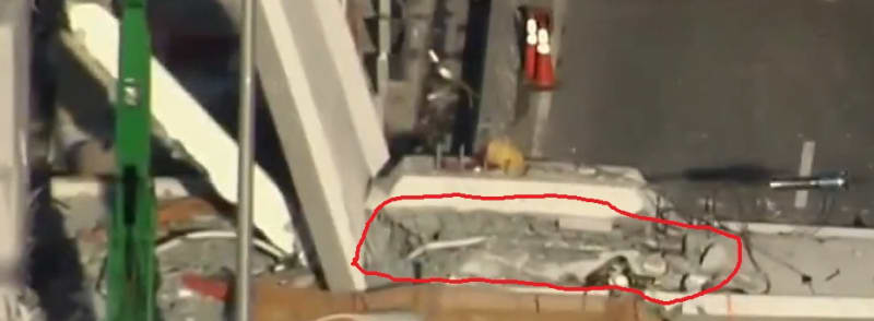
Not sure what you are pointing to inside that red annotation. Perhaps it's the white PT tube, and you're wondering if it's the lower PT tube of #11, which make the adjusting one the upper PT tube? (Except an upper #11 PT tube is visible in other photos.)
I the one you're looking at is more likely the most inboard of the canopy's PT tubes.
RE: Miami Pedestrian Bridge, Part V
A number of posters have referred to "the diaphragm". Is that the thick beam across the end of, and below, the deck, into which #12 extends at its bottom?
RE: Miami Pedestrian Bridge, Part V
Can be from canopy or is just rebar ?
Thank you all for response.
RE: Miami Pedestrian Bridge, Part V
Tendons too short seems highly unlikely to me. But why the need to expand the pocket?
RE: Miami Pedestrian Bridge, Part V
By the way I have done a pretty accurate wt. takeoff and excluding open conduits and ducts calculate that the total weight of the structure using 150 lb/ft3 for density of concrete and steel and 175' span is 1870 kips or 8318 kN. Reaction excluding verticals at each end and part of the canopy DL between 11 and 12 at the top would be about 887 Kips. as opposed to total reaction of about 935 kips. These loads of course are prior to applying any Load Factors which for DL alone I personally believe should be DL factor = 1.4.
I have not included added DL as per TY Lin of approximately 10 psf for a wearing course since I do not see any evidence that one was applied. The curbs that appear to have been added at each side of the walkway might add another 75 to 80 lb/ft of bridge not significant but should have added it anyway.
To continue this further lets calculate the moment in the beam using wt/ft=10.67, clear span between cL bearings = 172.5' = 10.67 x 172.5^2 /8 = 39682 k-'
With a depth of 15.8' the forces in the canopy and bottom deck are 2511 k compression and tension respectively.
Taking moments about the cL of the top flange and ignoring the diagonals we get 933 x (172.5/2) - 10.67 x(172.5/2) x (172.5/4) moment = 39682 same as above so compression and tension the same
The compression in the canopy and tension in the bottom slab are both excluding prestress in each which I do not know for sure. The two diagonals near the centre of the span are so small in area compared to the slab that their horizontal components in compression will be small and only determined by fixed joint truss analysis. The actual stress in the canopy due to DL only is 1.07 ksi. Unfactored stress in the deck without prestress is only 0.36 ksi. Due to prestress we know absolutely that the stress in the canopy was greater that 1.07 ksi and we know that the maximum stress in the slab with prestress would be a decent negative number but the slab has a gross area of 48 ft2 so it would take a huge prestress to fail it.
If the deck has equivalent of 11 = 19 x 6 tendons stressed to 70% I believe this would be about 11 x 0.7 x 4950 = 38115 kN or 8569 K so stress =-1.24 ksi due to pre-tension. Stress at the centre of the span would be -0.88 ksi after deducting tension due to dead load. This leaves added compression for full live load, tension load due to expansion of the bridge local moments etc.
In the critical first 6 feet of the deck which is the length of footprint of 11 and 12 together on the deck it is my opinion that only about 50% of the prestressing is effective in this shear zone giving only about 0.6 ksi of effective confinement stress without PT rods in 11. My opinion is that longitudinally 1 to 1.2 ksi is required and laterally 0.8 to 0.9 ksi is required for DL shear capacity without adequate deformed bars in shear to take the hor. and vert. components of 11. My opinion is only that (based on 53 years experience before retiring two years ago) and I would need to go back to the books on shear leg and confinement before making this more or less statement of fact.
With an angle of 36 degrees to the horizontal the approximate axial load in 11 would be 886/sine 34 = 1508 k so stress without PT tendons would be 1508/(22 x 24) = 2.85 ksi
With 2 tendons stressed to 250K each the stress would be 2008 / (22 x 24) = 3.8 ksi, the structure was able for a short time at least to support this stress. After release (we think) of say 250K tension the structure still stood. While releasing (we think) the second failed. Does NOT make sense.
Were they in fact increasing tension in the PT bars to close the crack instead of releasing the tension due to temporary loading or did the lack of confinement from the PT bars so weaken the deck concrete in shear that it failed along a plane about 180" long (around the footprint of 11 and 12) and on an angle through the deck to the first tensioning duct and then down to the bottom of the deck at right angle to the bottom of deck slope. Total area of this shear plane is about 180 long x 22 inches through deck = 3960 in to take the horizontal component in 11 of 1508 x cos 34 deg = 1220 k giving a shear stress of 308 psi horizontally and 887 k /3960 = 224 psi vertically on this shear plane. With what appears to be only nominal deformed bar reinforcing this shear failure is more likely to me than a combined stress failure in member 11 itself.
RE: Miami Pedestrian Bridge, Part V
"This confuse me. For my untrained eye looks like a PT bar but from where to where ?"
I believe that it is tendon duct or utility duct from the canopy but could be wrong.
RE: Miami Pedestrian Bridge, Part V
Thanks. I see that now in one of the night photos. Still seems an odd thing in such a highly designed structure.
RE: Miami Pedestrian Bridge, Part V
Looks like 11’s upper tendon to me.Nope. That’s not it. Maybe an empty duct left from where 11’s lower tendon ripped through? Tough to say.
RE: Miami Pedestrian Bridge, Part V
I was referring to the white snake going almost full length of the blister. Can only hope that the NTSB keeps a few larger pieces such as what is left of this cap and what is left of 11 and 12 to examine more closely.
RE: Miami Pedestrian Bridge, Part V
Yup. Sorry. I see that now. Hard to tell.
RE: Miami Pedestrian Bridge, Part V
I amended the earlier post on this question, due to confusion on my part as to which PT rod extends from top (thread is getting very long). Epoxybot reminded me it was the bottom rod. So I'll take another stab at possible explanation.
Member 11 fails in shear along yellow plane. With this primary shear failure, portion of underside of 11 spalls off along green line separating bottom PT rod from 11 and leaving it securely fixed in bottom slab. Now, significant secondary grinding occurs at base of 11 prior to bridge collapse, with vertical 12 still in place. Other members begin to fail around it--first top canopy, then finally bottom slab. Base of 12 finally gives way and 11-12 kicks out towards pier, bringing with it top PT rod. As bridge collapses to ground the distance between anchorage on top canopy and bottom slab, where bottom PT rod is still firmly anchored, shortens considerably. This could account for why bottom rod is pushed out while top is not.
RE: Miami Pedestrian Bridge, Part V
Stephen Nuchia (Electrical)26 Mar 18 21:27
"chris snyder near the end of thread IV sketches a counteracting compression force from the first diagonal of the south span. I believe that is a misunderstanding."
YES. Thank you - I understand now.. no opposing force because both mainspan and backspan are independent and not pulled together as if suspended segments held by cable stays. The backspan would be a "buttress"(?) once tied in, but not an opposing force - this would be a hokey design if it was meant to keep #11 from shearing.
LittleInch: aside from a video by Meerkat007 18-Mar-18 19:53 in 40ms segments (that may or may not show a projectile and 'dust puff' on north end), I agree the lower rod/jack could be forced out as the deck fell.
Meekat: I agree with Saikee119, that it could be an outboard duct for canopy cable, or could be the duct for the lower rod (not sure if rod/cable ducts are different diameters) - I can't tell... Here's a good photo (can see rod duct at left in shadow)
I'm going through all (about 1/2 through Part II now), but has anyone seen the dead end anchor of the #11 lower rod? Meerkat (18-Mar-18 19:53) said it appears to still be attached to the deck (under a pile of rubble). NTSB roll (Meerkat 19-Mar-18 06:48) got close when they had a measuring tape on the duct, but video didn't show the end.
RE: Miami Pedestrian Bridge, Part V
In the photos, it looks like you can see rebar going through the base of member 12 with missing concrete all around that goes through the entire member. Could just be from hitting the ground or contact with the pylon. Also still unsure if the large object that protrudes under half a second before the collapse is just the corner of the deck or an illusion. Photo quality is just to low, won't know anything for sure till NTSB releases more info.
RE: Miami Pedestrian Bridge, Part V
I agree 100% with you. That was what I do for root cause analyses. Load factor is for design. This is actual analysis or simulation to establish out the cause of the collapse.
RE: Miami Pedestrian Bridge, Part V
In very slow motion, the blob on the end of the deck rotates upwards as the deck pitches forward. I think it is just the corner of the deck.
RE: Miami Pedestrian Bridge, Part V
Nice photo and find. Where is that photo from?
RE: Miami Pedestrian Bridge, Part V
Part IV Incentive 24 Mar 23:01.. have seen others (Meerkat 23 Mar 17:53 and elsewhere online) but this was highest res. He's got good points there - all of it sticks in my mind (esp 'blowout' residue on that beam by the canal). Just noticed how rebar is bent out bottom of #12 (assume when it got pushed/broke from end beam), but ~straight from bottom of 11.
Been there a while, but just listened to this from Tony Pipitone.
http://wusfnews.wusf.usf.edu/post/week-later-agenc...
Said they were tightening #11 when it failed, and that WORK was being done, not a 'stress test' (~3:30-4:40), among other things.
RE: Miami Pedestrian Bridge, Part V
Never trust a computer with anything important...
RE: Miami Pedestrian Bridge, Part V
Just want to draw attention to this earlier post. The linked video, shot from approximately the same angle as the dashcam collapse video, is quite useful in showing the various visual distractions around the north end of the bridge, including a tree in the background, and a lamppost in front.
One may also see how the north west corner of the deck visually protrudes "beyond the end of the bridge" as the car moves east. However, it's debatable whether it does so at the right rate to correspond to the similar visual appearance in the dashcam video.
RE: Miami Pedestrian Bridge, Part V
Here is the effect of fitting the drawing to the end verticals (#1 and #12):
And here is the effect of fitting the drawing as closely as possible to members 2 to 11.
In each case I scaled the drawing uniformly with 1:1 aspect ratio.
This exercise is not perfect by any means.
1. Obviously perspective. I have scaled the overlay uniformly and positioned it to match the end verticals (#1 and #12) or the other members (2 to 11), so this is an attempt to get the elevation drawing to match the centerline elevation slice of the bridge.
2. We don't know if the 175 ft length is before or after the additional lane was added. Others in the thread reported that both ends of the bridge moved north by 11 ft, others think that the bridge got longer, but we don't know if 175ft is before or after this. If the bridge is actually 186ft (say), and I matched the 175ft drawing to it, that's only about a 6% mismatch, and might not be noticed in mismatch of the deck and canopy, for example.
I have attached a transparent gif of the elevation overlay in case it's useful to anyone.
RE: Miami Pedestrian Bridge, Part V
Not all variables are known for this, for example exact length of bridge (I used 175 ft), and amount by which the north end of the bridge overlaps the pier (I used 3 ft).
So if there's a single fold, and it's at the base of #10 and #9, then when that point descends about 13ft, the north end of the deck is clear of the pier. Of course, it might clear earlier, if the folds are more complicated. And there's some chance the deck might initially stretch a little, or pull the pier inward.
I've also noted that when the deck is on the ground, if it stayed in two contiguous pieces it would impinge on the pier. As it turns out, the north end of the deck rests just short of the base of the pier, consistent with the deck shortening a bit corresponding to multiple folds at several locations.
RE: Miami Pedestrian Bridge, Part V
http://www.vsl.com/business-lines/systems-and-tech...
If upper PT bar in 11 was tightened first and then lower bar tension was reduced with the jack, would that help explain how anchor for upper bar blew out while the one for the lower bar stayed in deck?
RE: Miami Pedestrian Bridge, Part V
https://www.google.com/maps/@25.7610545,-80.373640...
Youtube video everyone has seen, but now with overlay of members, frame-by-frame.
https://www.youtube.com/watch?v=jOe7CvVGqz4
New youtuber video. I have no comment on it's veracity at this point. (Update: Not to be taken seriously, absurd assertions made.)
https://www.youtube.com/watch?v=gS-pw5Pr8xs
RE: Miami Pedestrian Bridge, Part V
Two massive assumptions here:
1) the crack that was being talked about was at the base of the no 11 member with the deck or somewhere close to it
2) to "pull" the crack back in line they decided that the thing to do was tension up the PT rods bars as the anchor point was beyond the crack and it would then close up or arrest the crack growth.
However in doing so they actually then increased the compressive stress and force on the bottom of member 11 which found its weak spot and just went bang?? Maybe if the bottom PT rod was not straight, but bent over to anchor into the slab it actually started to pull out of member 11?
It wouldn't have taken much movement of member 11 (a few inches?) before it effectively lost all compressive force and as far as the structure was concerned then became redundant, leading to failure of the remaining parts of the structure.
I do always wonder when things are built in stages / separately, whether enough design and analysis is undertaken on those stages and not just on the final item. It's fairly clear that the second span would butt up to the first span on the other side of the pier and then combine to make the tower structure. This would then help spread the load and prevent a blow out type event.
As an aside, every time I look at that bridge from the recent dashcam footage or the one where someone wanders around the bottom deck just after it went up, those members just look puny.
Remember - More details = better answers
Also: If you get a response it's polite to respond to it.
RE: Miami Pedestrian Bridge, Part V
Yeah that guy keeps popping up in my search results too. Disorganized chaotic stream-of-consciousness blathering. He makes a few points that are not wrong, amongst a pile of misunderstandings about what has been reported, and jumps to conclusions with little insight into what is not known. At one point he claims maybe they put the entire bridge in backwards by mistake.
RE: Miami Pedestrian Bridge, Part V
According to Tony Pipitone after the bridge had been lowered into its final position the stresses in the diagonal members were released and finished.
However as cracks were discovered two days prior the collapse a meeting was quickly convened between D&B consortium, Owner FIU and FDOT. After the meeting the Chief Engineer (presumably from the D&B consortium) ordered the crew to do extra stressing work. This implies the stresses inside members No.2 and 11 were "changed" possibly as a mitigating measure to cure the cracks.
The NTSB did carefully use the word "workers were adjusting tension" when they released the news but Tony Pipitone information suggests the action, which triggered the collapse, was a repeat of something already executed before. The action that caused the bridge to collapse is therefore not part of the original design, which would have been reviewed, approved and documented formally but a quick fix to cure or minimize the cracks in a hurry.
Sound like a Chernobyl accident to me.
RE: Miami Pedestrian Bridge, Part V
Yes my response was partly amined at your previous post.
~Can you go back and look at / edit your post of 00:32 today? The pictures you have all of the upper tension rod in member 11. The lower one remained with the deck and was the one ripped out of the bottom side of member 11 that you can see in a lot of the previous photos. Your text keeps changing between upper rod and bottom rod.
I haven't seen the end point of the bottom rod in the deck in any photos or indeed if the rod ends were straight or bent over at the fixing points.
It's a damn pity we don't know where these mysterious cracks were that they were apparently trying to fix by maybe tightening up the tension rods.
Remember - More details = better answers
Also: If you get a response it's polite to respond to it.
RE: Miami Pedestrian Bridge, Part V
See for example my post on Part III: gwideman (Computer) 21 Mar 18 04:50
If you look at the associated NTSB video, there's no doubt that the lower PT rod of #11 goes into the deck. You cant see the anchor point because it remains within the deck concrete, probably in the end beam (aka diaphragm).
RE: Miami Pedestrian Bridge, Part V
No one, to the best of my information, has admitted that there were even photographs of the crack taken. As an engineer, I'm pretty sure that this would have been photographed numerous times.
Dik
RE: Miami Pedestrian Bridge, Part V
Either de-tensioning or tensioning of PT would be detrimental to this.
RE: Miami Pedestrian Bridge, Part V
In the diagram I note span attached to pylon. I have not seen any evidence collapsed section was attached to pylon. It's only connection to pylon was 4 PTFE bearing blocks from what I have seen.
Control of cracking.
http://concrete.t.u-tokyo.ac.jp/research/intro/mat...
RE: Miami Pedestrian Bridge, Part V
Fm 00:32
"Below looks like #11's upper duct and rod plate/nut protruding from a shattered end. "
this refers to the photos (easy to understand)
"#11's upper rod/duct (not pictured, at ground level - as you already know) was stripped from the member."
This should say "lower rod/duct"... thanks and sorry about that.
RE: Miami Pedestrian Bridge, Part V
The slide side is on the south side, the south side View C-C were mistakenly posted numerous times in part IV.
Post Edit Addition, likely the anchors had been tightened in place, this could explain the skid marks on the pylon, and "base of 12 missing?" posted by INCENTIVE in Part IV 25 Mar 18 04:53, and Part V 27 Mar 18 00:45:
On Plan:
RE: Miami Pedestrian Bridge, Part V
These two photos confirm (1) there is a construction joint at the interface of the walkway deck with No.12-11. (2) There are 4 vertical plastic sleeves or pipes, look like about 3" diameter to me, cast with the deck. Two on either side of No.12. There are some reinforcing steel bars, possibly for anchorages for other installation, and blue flexible small ducts or conduits, which I think could be tubes for grouting and de-airing the PT ducts in No.11.
There is nothing odd about the above items. However a construction joint if not properly prepared is a plane of weakness and can never be as strong as a monolithic construction without such joint.
The photo below is the best I could blow up to show the anomalies in details. It has been posted several time before.
I find the photo odd because
(a) The No. 12 has gone but the 4 white plastic pipes are there. The tilted one appears to have suffered some damage. If No. 12 was pushed out shouldn't it take out the 4 plastic pipes too? Concrete is much harden than plastic. So such condition would suggest bottom of No.12 was disintegrating when it left its position on the deck so that the small broken concrete pieces could not drag the plastic pipes away.
(b) The No. 11 has gone too. That is expected but shouldn't we find some reinforcement that connect No.11 with the deck here. I can see one or two small size bars around the foot of the investigator who was looking at the anchorage of the bottom PT rod of No.11.
(c) The first two drawings clearly show the 4 plastic pipes cast outside No.12 but the hole shows the 4 pipes are inside it. Has part of the deck also disintegrated too to leave behind the plastic pipes intact?
(d) Between the far end vertical and tilted plastic pipe, near the investigator's foot, the surface of the hole looks remarkably clean and straight as though it was formed by formwork and not ripped out from a homogeneous concrete mass. The only possible explanation to have such good surface "finish" is this area has been boxed out when the deck was poured. There afterward the 4 plastic pipes were installed and the void was filled with second stage concrete. Nothing wrong with this construction as it happens all the time on site. However it would be suicidal to do it at a joint that has to provide restraint to arrest a huge horizontal force from No.11.
(e) The only reinforcement of the deck in this photo is at one location a couple of small bars located between the undamaged vertical pipe and investigator's foot. The amount and size don't look like proper deck reinforcement to me. SO if this area has been boxed out did the workmen trimmed the reinforcement around it too?
To assist understanding I provide my own interpretation of other items in this photos.
The steel plates and other plates stacked against the abutment could be the remains of the bearings. The plastic pipes could be for the holding down bolts which in the proposed drawing only two were indicated and they are a lot far away from the No. 12. Other photos show no holes for the hold down bolts. gwideman other photos has depicted what looks like two holding down bolts on the abutment but the plastic pipes can also be conduits for other services. The back of the No.12-11 area has some 5 reasonable steel bars and a few smaller bar bent against the abutment wall. They could be the rebar linking No. 12 or 11 with the deck.
I have been haunted by the above last photo ever I saw it. Many of us talk about horizontal shear in No.11. A shear could only happen if one part moves while the other part remains stationary. Looking at the above photo and what have left in No. 11 and 12 make me think may be the supposed stationary part of the deck had moved out first to trigger the collapse. It is not really that far fetched if there is hardy any reinforcement provided to "restrain" the No.12-12 from moving outward. The concrete alone is unlikely to stop the two vertical triangular faces beneath the deck to shear off vertically. The back of No.11 could out by tension. Any reinforced concrete designer knows concrete has very resistance (in similar order as the shear resistance). The nearly untouched condition of the 4 plastic pipes does not inspire confidence the construction quality at this location. Furthermore if Tony Pipitone report were to believed during failure the tension adjustment has to increase tension, since the tension was released in the first round, then the crew was pressing their luck by pushing the No.11 out of position by increasing its axial compression.
RE: Miami Pedestrian Bridge, Part V
Better not make such assumption. The quality of this web site is we discuss facts and interpret them with our experience.
In my experience almost every concrete structure has cracks.
The bridge collapsed when the workmen were adjusting tension for the second time to fix the cracks according to a news report. It was reported the tension adjustment in the first round was completed and cracks were then discovered.
RE: Miami Pedestrian Bridge, Part V
Since a few people have reposted the earlier version of this diagram (gwideman 23 Mar 18 17:09 in Part IV), I thought I would update it to add a couple more details, and bring it in line with more recent observations people have made about various collapse photos.
RE: Miami Pedestrian Bridge, Part V
I'm not trying to raise alarm about the cracking or suppress its significance. I agree sticking with the facts is important here. During my youth I have witnessed thousands of yards of concrete being poured and cured, and while that gives me no expertise at all, I would be the last person to say a concrete structure can be crack free. I agree this web site is of high quality, I will strive for my comments to do it justice. Sorry for the misunderstanding.
RE: Miami Pedestrian Bridge, Part V
Something else to add to the discussion, and that is the fact that member 10 is seen punching through the bottom slab in the final moments of the collapse. Is this merely a random part of the process, something that is inevitable based on the geometry of the truss members? Or is the timing of this violent load reversal indicative of something else?
First figure depicts structure (member 2 -- top canopy -- member 11) viewed as an arch, with horizontal and vertical restraining forces at either end. Note member 10 in tension:
Second image is with horizontal restraining force removed at north end. This needs to happen prior to member 10 going into compression:
So my question is, can we deduce anything about when 11-12 base area disintegrates, thus eliminating the horizontal restraining force Hn, by looking to see when member 10 is driven through base? Or is there no connection whatsoever?
RE: Miami Pedestrian Bridge, Part V
Very good post. About the haunting photo of the demise of member 11, I would like to point out, if not already known, that this was a screenshot from "NTSB B-Roll". I would be pleased to read your observations on the full video if you have not seen it yet. You are on to something here. Thanks.
RE: Miami Pedestrian Bridge, Part V
As well all know, a truss is a series of triangles. To extend a truss, just add a triangle. To shorten, just remove a triangle. What seems to have happened here is that the brace function of 11 failed. This means then next triangle in series becomes the end of structure. Of course, there is no support under next triangle, so structure falls. So I believe 11-12-deck failed before deck and canopy buckled. Joint 9-10-deck would fail after 11 as this would be where the load path would "move" to. Ditto on joint 10-11-deck. The canopy-12 joint suffered very little damage as no real load was present there. I agree with the diagram you show with bold lines outlining the true parts of the truss.
RE: Miami Pedestrian Bridge, Part V
Took a while to find, but it's in Thread I, Tomfh 18 Mar 2:49, within the blown up version. When I compare this to the latest noted above by Jrs87 27 Mar 8:27, they appear to differ in that zone of the bridge. Can't explain why. Now I'm not sure what to believe!
RE: Miami Pedestrian Bridge, Part V
I realize that the remains of member 12 sitting on the pier closely resembles what member 12 looked like before the collapse, with a piece sticking below the main deck.
However if you go and look at some before and after photos using the re-bars sticking out the side of member 12, you can see that in fact the bit left on the pier was originally above where member 11 connected. There is a missing section of member 12 (the bit sticking out the end of the cross beam) which is either in the canal or is still attached to the end of the deck.
Remember - More details = better answers
Also: If you get a response it's polite to respond to it.
RE: Miami Pedestrian Bridge, Part V
https://i.imgur.com/9o6zVT1.gif
I'm gathering photos for another post, but it looks as if an explosive force (like dynamite) disintegrated the 11-12 member connection/lower ends while sparing the deck and its components (even the plastic).
RE: Miami Pedestrian Bridge, Part V
I'm new to the forum, but have been following from the beginning. I see a bulge at the 11/10 intersection below the deck, but I'm fairly sure it's an illusion.
In thread 4, gwideman's photo in the 24 Mar 18 12:37 you can see the traffic signals in the eastbound lanes in the distance.
A clearer view of the signals is in INCENTIVE's post at Mar 18 01:34. You can make out the bottoms of the westbound signals and signs below the deck. It looks like one of these signals was just behind the 10-11 junction in the Tomfh photogram at the time of the collapse.
RE: Miami Pedestrian Bridge, Part V
Fm Meerkat007 IV-23-13:43 - Member 12 damage overlap superimposed (slick photo)...
which explains why something looked odd with no sign of the PVC pipe this photo.
The 'clean' bottom end break looks like it sheared from the deck surface (as if a second pour - other photos show a difference at this point on the 'back' of member 12). The semi-circle face of 12 is odd... like an explosive blast hit it.
This makes me wonder what happened to the small extension 'block' (bottom of 12) with PVC pipe that was on the end of the deck. Photos of the other side of pier appear to show scrape marks along sides of the face as the deck slid down, but no scraping in the middle.
This photo also answers my above question... the top of 12 is mangled but it didn't break off.. looks like rubble held in place (with rebar?). The video appears to show the 12-canopy angle decreasing like a hinge, but it landed at ~right angle... there's also some web cracking up there.
RE: Miami Pedestrian Bridge, Part V
The blown up at the deck was obtained from NTSB video mentioned by members here.
RE: Miami Pedestrian Bridge, Part V
Unless enough reinforcement is provided the concrete on its own is not going to make it. The resistance area is just like a chute with two triangular shear faces on two sides and a rectangular base.
The other scenario is a horizontal shear along the top face of the deck or No. 11 went first pushing No. 12 out.
Actual failure could be a combination of several modes as depicted by gwideman.
This particular corner appears to be the weakest link. The tension adjustment action, if repeated as reported, is the trigger for its demise.
RE: Miami Pedestrian Bridge, Part V
No doubt, it could definitely be an illusion. The series of INCENTIVE's images, however, jumps from 0.38 to 1.0 sec, missing the time in question. If you run Gwideman's video, the "possible" punching of 10 through bottom slab occurs AFTER the falling bridge has passed before the traffic signals in question.
It's also possible that the hinging of bottom slab at 10 weakens this area and allows for 10 to punch through deck; i.e it's unconnected to timing of 11-12 zone failure and more connected to deck slab failure. Pure speculation on my part.
RE: Miami Pedestrian Bridge, Part V
At any rate, here are frames from Tomfh's animation:
The feature circled in frame 1 looked to me like the north west corner of the deck, and I had dismissed it. Not sure why it disappears in frame 4.
But what I only now noticed is the bulge feature circled in frame 4 that enlarges in frame 5, and then appears to blur in frame 6. In the animation, this appears to coordinate with motion of member 11, and seems in line with 11. In short, looks like it could be 11+12 punching out the end of the deck. Too fuzzy to be 100% convincing though, of course.
RE: Miami Pedestrian Bridge, Part V
I think I see what you are talking about. In a video posted by Tomfh in thread 1 at 18 Mar 18 02:42, I can make out a bulge just before the deck hits the ground.
RE: Miami Pedestrian Bridge, Part V
I have not seen evidence of No.10 punching through the bottom slab. However when no.11 lost its restraint and could not participate in withstanding the load the deck suddenly had to resist the system by acting as a flat slab. This it couldn't do and folded. May be No.10 was able to punch through in that particular moment. I tend to think whatever happen to No. 10 is a consequence and not the root cause of the failure.
You have done very good drawings on the bridge on their supports. You are right in thinking there has to be a horizontal reaction to counterbalance the horizontal component of No.11. The designer has pinned the hope the deck will provide the Hn. It could have worked if there are sufficient concrete and reinforcement to transfer the force across or dissipate the stress.
RE: Miami Pedestrian Bridge, Part V
One dashcam video from large truck. Some versions of the HD video are cropped (zoomed in a lot). Since the truck was moving towards the bridge at speed, someone held the bridge size constant in the crop (he used the term "dolly"). The artifact is perspective change with constant image size. This will cause distant items to move across the frame.
Another video is not a dashcam, but a cell phone video of a traffic cam monitor.
RE: Miami Pedestrian Bridge, Part V
I took the liberty of making a version of your drawing. For a split second after 11 failed to hold compression, the black shows compression "path". Bending moments and shear took out areas marked in red.
RE: Miami Pedestrian Bridge, Part V
My recollection is that Chernobyl was an operational accident. This incident appears to be more construction related and similar to the Hyatt Regency collapse where unapproved modifications to the design occurred. Forensics are probably focused on the construction revisions to the bridge design.
RE: Miami Pedestrian Bridge, Part V
The midspan chord forces of a truss can be estimated by simply dividing the moment caused by the end reaction at midspan by the depth of the truss. Assuming under dead load the resulting force in the lower deck would be resisted completely by the bottom slab post-tensioning so that the concrete stress in the concrete slab would be nearly zero, results in a significant amount of prestress. This prestress, or quite a bit of it, would need to be imparted into the slab prior to casting the diagonals and top slab otherwise the prestress would cause to much of a moment at the end of the span. This implies a cold joint between the diagonals and the top of the bottom slab.
The bridge code reduces the amount of shear friction that can be transmitted through a cold joint relative a monolithic joint. Therefore a cold joint requires more reinforcement to resist a potential shear friction failure at the join.
The vertical compression from the diagonal can be used to help resist a shear friction failure along the cold joint, but in the case of member 11, the horizontal force is larger and additional shear reinforcement is required. The contribution of the PT bars appears to have been limited so that a significant amount of mild reinforcement, fully developed on each side of the joint, would be needed.
There does not appear to have been much additional mild steel added.
The fact that the dead end of the lower PT bar in member 11 stayed with the bottom slab when it fell indicates that the failure plane was obviously above the anchorage. We don't know exactly where this anchorage was but it would have needed to be above the 8" drain pipe. This holds for the top dead end anchorage as well. These PT bars were not grouted and therefore would offer no dowel-action in resisting shear on the assumed failure plane (cold joint). If they crossed the failure plane, their stress component perpendicular to the failure plane would help clamp the joint together, while their tangential stress would tend to cause a shear friction failure. Again the angle is such that the latter would be dominant.
At this point it looks like member 11 could have failed at or near the deck surface taking out member 12 in the process. This would destroy the truss action and lead to failure.
If you compare the end diagonal connection of the FIU bridge to the end diagonal connection of a steel bridge, the former appears to have been under designed. There should have been PT bars or PT strand in the bottom slab, in-line with the diagonal on the centerline of the bridge, to transfer the horizontal force in member 11 into the bottom slab (chord) so that a less predictable mechanism such as shear friction would not need to be relied on. This was not a robustly designed bridge. It appears to have been designed in a way to speed construction, which can happen on design-build projects where the contractor has a significant role in managing the design details to aid construction.
The design was also meant to be innovative, pushing the boundary of normal practice. Engineering firms pride themselves in their ability to do this; it is a way of distinguishing themselves from others. There is nothing wrong with this as long as there is a significant amount of attention given to design and detailing, along with adequate oversight in the form of an independent design and detailing check by a competent engineering team, and peer review by a team of industry recognized experts to ensure that nothing is overlooked. This level of oversight would not be unusual for a project that sells itself as being innovative. It is what is required of such designs and seems to have been lacking on this project.
RE: Miami Pedestrian Bridge, Part V
Dik
RE: Miami Pedestrian Bridge, Part V
Yup... I still use 3D frame programs for analysing and use spreadsheets for design... don't have confidence in letting the machine do all the work. I've been using SMath Studio (free MathCAD like program) a lot these days, and, it sure beats a sliderule... and, it would have likely stood up... I was a bit curious how they managed the lateral stability issues with substantial unbalanced loading, and, if they used the cable stays to help.
Dik
RE: Miami Pedestrian Bridge, Part V
You should get out more... I have my 48GX in front of me...
Dik
RE: Miami Pedestrian Bridge, Part V
Far too late for that, I'm afraid
RE: Miami Pedestrian Bridge, Part V
I think the 'bulge' is Member 12 dropping down and rotating as the bridge fails - we are seeing the side / back of it as it drops and rotates in towards the carriageway - as it rotates more of it 'comes into view' and appears as a 'bulge'.
I've not seen much which dissuades my opinion that the base of 11 sheared (either in the member itself, or at the joint with the deck). Still to be confirmed, but I think this was probably instigated by the removal (reduction) of pre-tension in the member which either reduced confinement of the concrete at this joint (or otherwise affected the way shear was being resisted, perhaps partly in tension of the tendons). The loads then snapped the deck at 10, and as the canopy falls it pulls (rotates) member 12 down with it. This snaps the base of 12 out of the back of the deck.
RE: Miami Pedestrian Bridge, Part V
No doubt. Virtually all of what we see is secondary failure. Studying it has a certain academic value. But working backwards through the series of cascading events my lead back to the primary cause.
Once the primary failure takes place, whether its shear of 11, punching/crushing of 11-12 base, pullout of 11-12 from end, etc, loads are quickly redistributed throughout structure. And the structure is likely to behave differently depending on which was the primary failure mode. We're fortunate to have video of the collapse. Sadly, though, it may be to low a quality to get at root cause of failure.
RE: Miami Pedestrian Bridge, Part V
A structural engineer said software is good for calculating loads, but not good for connections (analyzing and flagging as weak). Is this true? From what I've been reading here at different points (most recent pontduvin above), it takes more experience and understanding than just numbers to come up with a good connection. Especially in a bridge like this - concrete with little steel reinforcement. All the "bridge guys" here have said that connection is far too weak - hard to believe someone involved with this didn't notice.
Which reminds me...
Saikee119 (above 13:54): "The steel plates and other plates stacked against the abutment could be the remains of the bearings."
There didn't seem to be any plates/bearings at this end. They're at the other end in photo below.
Could this steel have been some reinforcement somewhere in this joint? (without a "setup/pour" spec it's hard to tell where rebar and other steel might have been used). Seems large plates like that might make an area weaker, though they'd remain intact if the connection 'exploded'.
RE: Miami Pedestrian Bridge, Part V
think that everyone may be jumping to an incorrect conclusion... The discussion is based on preliminary documents, and, unclear photographs... I think we're looking at the right area, but, without specific information do not necessarily have the correct mode of failure. This, hopefully, will improve as additional information is made available.
Dik
RE: Miami Pedestrian Bridge, Part V
I use computer programs for analysing structures and do a quick 'thumbnail' check for reasonableness. I don't rely on the program to do the design...I'm a bit of a dinosaur for this and use my own spreadsheets. I don't trust machines that much, and, am afraid of being 'lulled' into accepting their design.
Dik
RE: Miami Pedestrian Bridge, Part V
1) The PT strands each side of 12 appear to be smaller than originally planned, in the concept the smaller tendons were outboard of the 6-19 tendons, they appear here to be inboard, not sure number of tendons in these. Affects the local confinement stress in the area of 12 due to shear lag effects in the first few feet. Possible cause would be crowding of service, grouting and other ducts in this area.
2) The shear plane appears to at least partially follow where the cold joint between 11 and 12 would probably be because of the pour sequence. I am starting to be convinced that the actual area of the shear failure is less than it should be with proper reinforcing meaning much higher shear stresses. Quite a few of us believe that there was a major shear failure at the base of 11 and 12. The only disagreement that I can see is on the failure surface. regardless if they were adding or releasing tension in the PT bars to achieve lift off they would slightly increase the load and possibly this pushed things over the edge.
RE: Miami Pedestrian Bridge, Part V
Any idea when that is likely to occur? Is there a scheduled NTSB update briefing?
RE: Miami Pedestrian Bridge, Part V
Link
RE: Miami Pedestrian Bridge, Part V
*sigh*
because I'm a dummy and misread several photos in a row.
PT bar with tensioning equipment still attached is definitely the lower one as others have stated.
RE: Miami Pedestrian Bridge, Part V
TW
RE: Miami Pedestrian Bridge, Part V
Wow - that one sure makes the mysterious 'bulge' or 'puff' look more like a definite breakout.
That link Dilbert gave points to DailyMail , which appears to be a copy of a youtube by one 'officialjoelf'
Here's the youtube "officialjoelf" version which is clearer yet. I wonder were he got it...
https://youtu.be/Ucflj-MsJBI
and you can play it back at 1/4 speed with the youtube controls. I will try to figure out how to single frame it , for now here's four images you ought to see. About seven seconds in...
( i hope this youtube isn't some kind of hoax)
just before start of collapse
Next frame, as close as i can control playback. The apparition appears immediately, not as if it were camera angle.
A few frames later
The apparition gets pulled back in
Thanks @ dilbert for finding the clearer video.
Looks to me like something got slammed out behind and hit a definite limit to its travel, then was yanked back in during the fall.
What do you guys think ?
EDIT --- AHA ! Youtube single frame control: pause, then press period ( . ) for ahead one, press comma( , ) for back one.
.
Never trust a computer with anything important...
RE: Miami Pedestrian Bridge, Part V
saikee119: thanks for the drawing. From other photos, the 11-12 connection area is "busy" with large horizontal PVC pipe underneath, several 3"(?) vertical PVC pipes next to 12 on both sides, and tension cable ducts near the surface. It was a weak area, but still held the lower PT rod anchor plate as it ripped away from member 11.
I no longer think a large chunk broke from the deck, but that 11-12 sheared as gwideman shows in IV-23-17:09. Appster has construction photos (IV-23 Mar-22:21) - it appears the deck was poured first (photo 6,7), then members second (photo 8), though can't tell how end/diaphram was done, or where PT rod anchors were set (FIU print only shows top). I think the shear/break point was the deck instead of going into diaphram - there's a 'box extension' on 'back' of #12 (where PVC pipe comes out) with what appears to be a "pour line" - this is where 12 broke/sheared, but the ends of 11 (4' to 6'?) and 12 (2' to 4'?) completely disintegrated.
Below is a (very) rough drawing of how I think things ended up (I can only do 90o rotation - using sailee119's for outline).
Bottom of 11 and 12 were shattered (red dots) - while rebar from bottom of 11 was still fairly straight (I don't understand how this could happen). It doesn't seem rotation of the north end, with ends of members sliding across/landing on top of pier, would have enough force to shatter that much rebarred concrete.
(Note: I thought this end was similar to the south end 2-3 PT rods, but print shows top of upper rod a dead end anchor (adjusts from below) and lower rod adjustable from top. Anchor plate spec is 8"x12" but 11's upper tube plate in photo resting on top of pier looks smaller (like those I see on PT rod sites for the nut end). Both rods on 11 were adjusted from top, and they appear to have a LOT of threads showing (I don't if this is normal). I tried to find a good photo of 2-3 since it had been adjusted earlier, but couldn't find any with good detail (2-3 blister photos show the top opened up/chisled(?) larger, similar to 10-11)
RE: Miami Pedestrian Bridge, Part V
The underside of the deck is taper when it was on the four transporters. In the final position the support is the flat bottom of the downstand beam (or end beam). Alignment should not be a problem for a simply supported condition. I expect the bearing pads to have some compressibility to take out any small unevenness.
4 Transporters tied together by 2 huge girders supporting the bridge with timber wedges
I do agree with your sentiment that the structure could have suffered some damage in the move. On the transporters it was confined by large timber wedges. Although the transporters were bolted together by two huge girders to form a rigid table but the jacks were not and definitely have some flexibility. Since one end acts as a pivot while the other traveled 1/4 of a circle, any flexibility in the jack supports will cause the 4 supports not moving simultaneously and the bridge will be bent laterally.
I agree the bridge in your link did rock from 0.44 to 0.50. While this does not necessarily translate into damage but it clearly shows the cantilever did experience some disturbing forces. My approach would be include some dynamic load as a load case in the analysis of the maneuver.
When cracks were reported and confirmed not affecting safety at the north side, same side when it rocked, my initial thought was the bridge might have suffered some damages from the dynamic condition.
RE: Miami Pedestrian Bridge, Part V
Good drawings! Seemingly each day we are getting closer to what happen.
As Gwideman has pointed out previously you need to be careful with the information as Appster posted on 23 Mar 18 22:21 is a animation and not the real thing. While it depicts the method well we do not know exactly the details of the pours. If you watch the video the whole bridge was constructed with a single workman seen. Magic?
RE: Miami Pedestrian Bridge, Part V
Perhaps the puff is part of the banner zip-tied to member 11. When 12 falls, the puff goes away as banner is pulled down with it. Banner remnants can be seen between deck slab and pylon in NTSB video. Note how the banner shredded on member 3 in clear view on the truck dashcam video.
RE: Miami Pedestrian Bridge, Part V
slow motion
As the video starts, note the puff of white dust to the right of the worker on the top of the canopy. The dust than dissipates and then returns, maybe blown away by the wind? The dust would appear to show that the worker was chipping away the concrete at the time of collapse, and not post-tensioning. There is then a puff of black on #12, then a puff of white dust on #12 as the collapse begins.
It appears that the bridge fell during the preparation for post-tensioning so that would indicate that the bridge was already unstable or damaged.
https://uk.gofundme.com/navaro-brown-funeral-expen...
RE: Miami Pedestrian Bridge, Part V
Do correct me if I misinterpret your thought of your post on 27 Mar 18 21:21.
I believe the PT strands you mentioned on either side of No.12 should be PT rod. The diagrams of them have been provided by Alfie.Tx on 27 Mar 18 13:49.
The drawings would suggest they are holding down bolts for the designer to fix both spans at the pylon position but allow the two opposite ends to freely slide to mitigate the longitudinal thermal stress.
RE: Miami Pedestrian Bridge, Part V
The plans show spreader plates on top of transporter units across both transporters. The transporters are also positioned on the ends of the bridge.
RE: Miami Pedestrian Bridge, Part V
Why the Miami bridge broke - Prof Simon
--
JHG
RE: Miami Pedestrian Bridge, Part V
sure seems plausible . At the instant of that frame you posted, the tendon hadn't yet unzippered from #11 . As the deck continued down with #11's bottom hung atop pylon, it ripped the tendon out straightening rebar as seen in NTSB pictures ?
Holding that thought to see if it withstands scrutiny....
Thanks for the feedback ! old jim
Never trust a computer with anything important...
RE: Miami Pedestrian Bridge, Part V
I am afraid you are behind with the history. First the north side has a concrete barrier making the original transporter configuration too much work. A change was introduced probably necessitated the PT rods introduced in No. 2 & 11 as No.11 according to the proposed drawing has no PT system. The revised transit support arrangement has two overhanging cantilevers causing No.2 and 11 suddenly taking tension not anticipated in the proposed drawings. The change broke the bridge indirectly!
This was how the bridge supported during execution.
You can see the concrete barrier or divider here. It broke the fell bridge by locally hogging when the bridge failed by sagging. The sagging point is at the lower left corner of the photo.
RE: Miami Pedestrian Bridge, Part V
I calculated the stress in 11 on the pier with its axial load and assuming two PT bars at 250K tension each. Under dead load only the axial stress in 11 with a reaction of 887 kips after removing DL of 12 and half of canopy between 11 and 12 = 1508 k/ 22 X 24 = 2.85 ksi with no PT bars. With the two PT bars at 250k axial stress would be 3.8 ksi. If one was tensioned to 280 kips (maximum at 70%of ult.) then if one was taken to ultimate of 390 or 400 K the average axial stress would be 2178k /22 x 24 = 4.125 ksi average at the moment of ultimate breaking strength. After the break the average stress would be about 3.38 ksi with axial stress of 2.85 ksi plus a moment of 280 x 0.75 (allowing 3" to cL of PT bar = 210 k-'. With S= 22 x 24^2 /6 = 2112 in3 bending stress would be 210 x 12/2112 = 1.19 ksi. After failure of the tendon if it actually did fail the maximum comp. stress in 11 would be 2.85 + 1.19 ksi = 4.04 ksi. this is only slightly above the stress with DL + 2 PT bar stress of 3.8 ksi. Was the shock of the ultimate failure of a PT bar if true enough to fail a borderline structure or was the moment created by one PT bar enough for 11 to fail in bending.
Why would they even consider changing anything if the structure was so borderline. If you keep stretching a PT bar and the load does not increase better stop right away. Looking at the one dash cam video though it does appear that 11 deforms too much at the top and bottom before the failure. Video is of low quality but NTSB could have NASA or someone make the video clearer by computer enhancement.
Sorry Prof Simon but I am still a skeptic who of course does not even know for sure what strength of concrete was used in the web, deck or canopy.
RE: Miami Pedestrian Bridge, Part V
I should say my assumptions differ from gwideman slightly but the overall result is a reasonable match. He assumed the sagging point 36.83' from the north edge while I used 37.13'. I believe he clear the seating width for the full end beam 2'10-1/2" width when the bridge drop 13'. I assume the 175' span between bearings so my deck clearing off distance is half of him and so my drop is only 9' approximately. However my graph does show a 13' drop if the clearing distance is doubled.
The above graph also depicts how much distance the edge of the fell deck from the face of the abutment. Both gwideman and I assume the ground level is 20' from the top of abutment. When the fell bridge lying flat on the ground my graph shows a clearance of 0.25" distance which is not too far off from the actual structure.
The graphs assume the broken segments can be summed back to the original 175 length but in reality with concrete spalled and structure folded at more than one location the total length of bridge could have changed. Nevertheless the blue graph above would suggest the deck was moving south if something were protruding north during the collapse. Therefore it may be a possible explanation for why the protrusion retracted.
RE: Miami Pedestrian Bridge, Part V
A famous example of what happens when this is not done is the $180Million Sleipner A-1 North Sea concrete oil platform that sank in the Gandsfjord outside of Stavanger, Norway in 1991 when it was undergoing ballasting in preparation for the addition of its drilling rig. It failed in shear as a result of poor geometry and inadequate reinforcement. The failure is shown below. If that T-headed bar had extended out to the far surface it might not have failed.
RE: Miami Pedestrian Bridge, Part V
No I was referring to the strands immediately either side of 12 in the deck, not in member 12 itself. The concept drawing section of the bridge shows 6 x 19 strands either side of 12 and smaller or fewer strands outboard. The smaller bundles seem to be inboard and would cary less tension in the most critical area. The post you refer to showed bar in member 11 and in bottom of 12.
On another subject
Does anyone here have any evidence besides the professors video to verify that they were actually attempting to add tension to the PT bars to close a crack. If true no experienced crew would keep jacking on a PT rod if the tension is not increasing; either the bar is into the yield zone, anchorage has failed or something else is not right. From 70% if that is what it was at to failure would involve more than a bit of elongation. Did they or did they not know the stress history of these PT bars.
And another. Does anyone have any idea what PT strands were planned for the canopy and when these were to be tensioned before moving the bridge.
RE: Miami Pedestrian Bridge, Part V
Good dwg of the concrete "Y" failure. Please look at the Columbia bridge failure thread: There, another "diamond" diaphragm separated very nearly identical to the oil platform failure you show.
RE: Miami Pedestrian Bridge, Part V
The crews have to increase the tension in order to back off the nut to relieve the tension.
The failure appears to be shear or crushing of member 11.
The PT rods do not appear to be broken.
The crew had the jack on the lower rod of member 11. In some of the pictures he lower end of the rod appears to be anchored into the deck. Had the rod broken it is doubtful that it would have zippered out of member 11 as much as it did.
Bill
--------------------
"Why not the best?"
Jimmy Carter
RE: Miami Pedestrian Bridge, Part V
It's pristine, clean, clear of ANY concrete blocks or remnants or pieces. Only a light coating of dust. As if the rebar were "oiled" or painted/didn't adhere to the concrete around it.
With the 4 inch dia plastic drain pipes at each connection, would that not also contribute towards a weak jint at each connection?
RE: Miami Pedestrian Bridge, Part V
The clean bars were prestressing bars, not normal grade reinforcement. They were not bonded, just anchored at each end. Whether they were to be bonded by grouting in the final structure, I don't know.
RE: Miami Pedestrian Bridge, Part V
The faster frame rate and looping allows us to make better use of our visual system to see continuity of action.
(All are cautioned that this is still just 7 frames of fuzzy zoomed dashcam video, albeit with Tomfh's "dolly zoom" enhancement).
Half-size version below, full size version is in the attachments. (A bit overpowering to post in line, I thought.)
[Edit: I decided to post slightly slower version: 160ms per step. If dashcam was 60 frames per sec, then this is slowed by a factor of 10]
RE: Miami Pedestrian Bridge, Part V
Is this what you are looking for the strand arrangement for the canopy and deck?
It is page 112 of the 173-page MCM_FIGG proposal. The web page has been cited several times in this site. Think EingineerEIT first gave the web address on 16 Mar 18 15:04 in Thread 1. I believe it in in FIU site too.
RE: Miami Pedestrian Bridge, Part V
interesting looped video.
I'm pretty sure that as the collapse occurs you can actually see the bottom of member 11 and 12 bursting out of the end before they get dragged back into their final resting place. The top of member 12 has some bars sticking out and if you follow them down then you see it actually, for a short time sticks out the far side of the pier. Hence why there is debris from member 11 on the re-bar.
As I've said a few times, this collapse is so sudden and so brutal it is impossible to be 100% certain what is cause and what is effect. Maybe the bottom of 11/12 became detached from the base as part of the collapse, maybe it moved a bit and then became detached. I think as Hokie said in an earlier part of this post, we may never know, only establish a number of possible causes.
I'm not actually sure now where this post has left to go until new information is released by the NTSB. I think by now all reasonable theories and conjectures have been aired and we probably all have slightly different views on which is the most likely, but with so much missing critical information (e.g. reinforcement details, were they loosening or tightening the PT rod at the time of collapse, did the rod break or not, whether there were construction changes from the drawings, where was the crack, was there a cold joint, is there a block of concrete in the canal etc etc) I think we're in danger of just recycling and endlessly looping around.
Remember - More details = better answers
Also: If you get a response it's polite to respond to it.
RE: Miami Pedestrian Bridge, Part V
Nice video concentrating on the failure mechanism. I find it very convincing.
I don't know about others but I would say the bridge failed because No.11 lost its restraint at the bottom. No.11 then became a moving mechanism (not a static component) carrying out of balance forces. Without No.11 the remainder of the bridge could not cope and bent at the bottom of No. 10&9.
I would disagree with the bridge failed first at the canopy joint at the top of No.11&10 because that would imply No.11 could still function as a strut then. The canopy section above No.11 has no structural duty except carrying the PT strands' anchors. The canopy in its final position will be in permanent compression. Therefore a complete removal of the end section of canopy on top of No. 11 plus a complete loss of the PT strands, which beneficially brings about a reduction of compression in the canopy, should not matter and theoretically cannot not cause the bridge to fail.
The reason why No. 11 lost its restraint (root cause of the collapse if the above is believed) and how the collapse was triggered are two different matters.
RE: Miami Pedestrian Bridge, Part V
Would you loop the slow motion version that is posted on youtube? The slower speed helps to pick out additional details. It appears to show a white cloud of dust next to the worker and on the side of member #12.
Slow Motion Link
RE: Miami Pedestrian Bridge, Part V
I think we can conclude none of the rods broke because
(1) NTSB news release last paragraph confirms south side all PT rod completed. North side one PT rod done and workmen were adjusting the second rod when the failure occurred.
We now know the last rod worked on still had a jack attached after collapse and it was the bottom one of No.11.
(2) NTSB B-Roll video clip shows the bent threaded PT rod, how it rip out the concrete and broke the shear links in No. 11
(3) If a PT rod broke that means concrete won and no crushing, No.11 has less axial load making it less likely to push out of its restraint and the bridge should still stand. If we insist may the PT rod had broken at a point hidden underneath the rubble now then the bridge failure had to be caused by the energy released by the breaking of one 1-3/4" PT rod. In that case we should expect to see the attached jack flying out from the bridge in some Youtube videos.
RE: Miami Pedestrian Bridge, Part V
I agree with you that it seems highly likely that the rod did not break as otherwise why would it rip out of member 11? I just put it in the list because we don't know 100% for certain that it didn't and there has been a lot of discussion about if it broke or not. The NTSB report just says they were "adjusting" it. It doesn't say if it broke or not. We shouldn't start reading words which aren't there.
Equally the balance of probability is now that the rods were being tightened after apparently being released once the initial bridge installation was complete, but again, we don't know 100%.
Remember - More details = better answers
Also: If you get a response it's polite to respond to it.
RE: Miami Pedestrian Bridge, Part V
Agree 100%
Check out Eng-Tips Forum's Policies here:
FAQ731-376: Eng-Tips.com Forum Policies
RE: Miami Pedestrian Bridge, Part V
- The mass that appears to shoot out the north end seems to be aligned with member #11, even to the point that is seems to be exiting from lower than the deck elevation almost along an axis if #11 was extended out the end of the section.
- It also looks like initially the base of member #12 kicks north (out the end) initially.
My (uneducated structurally-wise) opinion of what it looks like to me:The 11/12 joint sheared from the deck (as many seem to believe), possibly from relieving the PT which would reduce the clamp loading (shear resistance) of 11/12 to the deck. This initially punched out the north end moving the bottom of 12 with it. This is the "blob" that appears. Then as the entire structure collapses it pulls 11 and 12 from there position of being pushed off the north side but because they were still attached to the canopy they get drug south back over the top of the support. This is the point when "the blob" seem to be sucked back into the structure.
I contend that "the blob" may be the bottom of 11/12 as they sheared to the north and then got pulled back the other side as the canopy/11/10 collapse to the south.
RE: Miami Pedestrian Bridge, Part V
On your second point chris snyder on 27 Mar 18 04:09 posted a link to wusfnews. Tony Pipitone has reported like you said " the rods were being tightened after apparently being released once the initial bridge installation was complete". Pleople who have doubt should listen to the audio recording as from UK I know nothing about Tony Pipitone but he is a respected investigative reporter for NBC and his description of the event appear to be all factual as I cannot imagine he could say what he said unless being told by the relevant parties responsible regarding the previous transitional tensile stresses have been released before the road was open and then the chief engineer on return from the cracks meeting ordered some members to be re-stressed again.
In the discussions here we learn from each other and try to weed out information which is not factual. As a practicing engineer we learn from mistakes that is why people are interested even we have absolutely no influence on the actual investigation.
RE: Miami Pedestrian Bridge, Part V
Not so fast.
1) Don't believe the post-tensioning procedure has been seen. This should be documented as a work procedure.
2) Does adjusting the post-tensioning procedure include chipping out space in the anchor blister for the hydraulic jack? Was the worker chipping concrete at the time of collapse?
3) Why does the post tensioning rod nut extend so far into the anchor blister?
4) What is the white dust that is seen around the worker shortly before the collapse?
5) Final as-built drawings have not been released and some parts of the structure are different.
It is all conjecture until what the post-tensioning crew were doing is documented.
RE: Miami Pedestrian Bridge, Part V
That's an interesting request, however at the moment I don't have a method for grabbing video from YouTube. I know there are programs and web sites that claim to do that, but last time I looked they all seemed very shady, wanted you to install potential virus-infested software, or sign up for spam. (But I'm open to suggestions from anyone with a non-shady method.)
That said, a couple of notes:
- Your link points to: https://www.youtube.com/watch?v=D6pGzgm4zZ4, a channel belonging to Zac Doyle. It is a slow-motion video with impressively smooth motion, implying a lot of distinct frames of video.
- That video's notes point to Zac's interesting blog post at: http://zldoyle.blogspot.com/2018/03/photogrammetry-of-fiu-bridge-collapse.html
- That post in turn points to Zac's original source for his video, a YT channel named OfficialJoelF: https://www.youtube.com/watch?v=Ucflj-MsJBI. This is almost certainly not the original, and is a fast-motion video, though the notes say "I decided to slow down the dash cam and zoom in".
- A commenter on Zac's post pointed to this video https://www.youtube.com/watch?v=jzbfJF5iVpI, which provides a longer span of time and a larger frame view, and is even faster-motion. (Fast motion really just corresponds to the dash cam frame rate being far slower than 60/sec, which is a reasonable way to economize on data storage for dash cam purposes.) But that link has only a few views, so seems unlikely as the original upstream source.
Anyhow, Zac managed to produce a video running at some slow-motion rate that nonetheless has very smooth motion, supposedly based on a fast motion video with very obviously not-smooth motion. There's something significant missing from this story.Either Zac has access to a video that has a lot more frames per second (and mistakenly linked to the wrong source), or he has interpolated the sparse-frame-rate video to produce intermediate frames. Zac's article talks about interpolation, but I initially assumed that was with regard to interpolating identifiable points in the image. I don't know much about interpolation of video frames, but presumably that can be done using a morphing technique, given enough identifiable points from frame-to-frame of the original video.
Bottom lines:
1. It would be useful to know where the original original dash cam video is, or came from, and work with that raw data as a starting point.
2. We should be cautious of enhancements, as any enhancement "adds clarity" by imposing its model of what happened. For example, an enhancement might use linear interpolation of motion between frames to generate new frames. In any case, we should at least be aware of what enhancements have been performed.
RE: Miami Pedestrian Bridge, Part V
But photos of this same area during the roll in show the same uneven rough surface around these anchorages. Why is that? Was there some uncertainty surrounding these anchorages before the roll in that required their anchorages to be exposed? Why would access have been a problem if the plan had all along been to de-tension the bars after the girder was placed? If that was the case why not properly form a ressess for the future work?
I agree, more info is needed in order to go further.
RE: Miami Pedestrian Bridge, Part V
From an earlier post about the pvc pipes:
From the end of the video taken by the camera on the end of the bridge during the move:
RE: Miami Pedestrian Bridge, Part V
So not really a crack, but sort of a crack....
RE: Miami Pedestrian Bridge, Part V
[...] 2) Does adjusting the post-tensioning procedure include chipping out space in the anchor blister for the hydraulic jack? Was the worker chipping concrete at the time of collapse?
If the de-tensioning had previously been completed and they were re-tensioning, why would they need to chip out space?
RE: Miami Pedestrian Bridge, Part V
Also to sailkee119 I thank you for the information on the deck and canopy tendons. Appears then that the 6-12 tendons were swapped from outboard to inboard in the deck if we look at giideman's post of 27 Mar 18 15:04. Less pre-tension in the critical centre area of the suspect failure zone.
RE: Miami Pedestrian Bridge, Part V
Pure speculation, but maybe as per the original design, as these tendons were supposedly only there for the lifting process when members 2 and 11 were in tension, were then de-tensioned not long after the bridge was put on the piers and hence their job was done so they were then grouted in to smooth off the top bullets and avoid any water getting into the tendon tubes?
If so then it shows that this probable re-tensioning was not a planned occurrence but a reaction to this mysterious crack.
Remember - More details = better answers
Also: If you get a response it's polite to respond to it.
RE: Miami Pedestrian Bridge, Part V
Additionally there must be enough added length to attach the tensioning jack.
There may have been a little extra length as a safety factor.
Hence the extra length of the rod protruding out past the nut.
Although the rod in member 11 was not permanent, normally the cavity in the blister must be deep enough
that the protrusion of the rod may be completely covered with concrete or grout when the final tension was set.
Bill
--------------------
"Why not the best?"
Jimmy Carter
RE: Miami Pedestrian Bridge, Part V
Member #11 was buckling as soon as collapse began, and fell straight downwards. If #11 slipped off I'd expect it would keep going?
This is an impressive video, but be careful of using it to study the details. Most of the frames are fictional.
RE: Miami Pedestrian Bridge, Part V
The extension of the PT bar beyond the nut must accommodate AT LEAST half the length of a mechanical threaded coupler (see photo below, which are 8-1/2" long for a 1-3/4" PT bar). A short, temporary "pull bar" is most often used, and it connects the stressing jack to the PT bar assembly. A stressing stool (usually a custom-made heavy-walled tube with a annular bearing plate, and a reinforced side-wall cutout) is used that bears on the tendon bearing plate, and enables the pull bar, nut, washer, and coupler to freely elongate, and also enables the stressor to then adjust the nut.
RE: Miami Pedestrian Bridge, Part V
I'm posting this to provide some background on the original dashcam video, and hopefully explain some of the misunderstandings about the many versions of it that are floating around. (Provided I insert the links correctly!)
The earliest known post of the dashcam video was made by Twitter user @o2webdev. If you search for that name you'll find that his real name is Oscar Fuentes, and he has since deleted almost all his media accounts after his twitter name was mentioned in several web articles. He seems to be a software guy rather than a truck driver, so he may not be the original, original poster.
There are several blurry, low-rez duplicates of his video floating around, but only a few versions exist that appear to be "high-quality" direct copies. One of these copies was previously noted by gwideman 28 Mar 18 16:21 - https://youtu.be/jzbfJF5iVpI - but the poster doesn't know who shot the original video. It was also uploaded on the 18th.
The earliest known HQ copy I could find was a shortened version posted March 16th, on the Twitter account of Joel Franco - https://twitter.com/OfficialJoelF/status/974834499140898817 - He properly identifies his source as @o2webdev.
Franco also posted a "slower" version of the original that "zooms in" for the second half. I've seen some confusing comments about similar videos, so here is a simplified explanation of what is going on to create a slower, zoomed-in video:
The dashcam video was shot at five frames per second (5fps), or one frame every 200ms. When played back at the PC standard of 30fps, this causes the video to run at a speed that is 6 times faster than normal. To create the illusion of a slower, smoother video, Franco used an 2-D interpolation routine to calculate in-between frames. Simple averaging can't be used because each pixel moves to a different X-Y location in a following frame.
Other videos that look like they're running at "normal" speed, but have a dream-like quality, were created by interpolating up to 5 (FIVE!) intermediate frames between each pair of original frames.
Other editing schemes create the illusion of a slower video by inserting duplicate copies of each frame. This results in a jerky motion, like old 1920's motion pictures. Padding an already interpolated video with duplicate frames slows the playback speed by at least a factor of four: frm1-dup-int12-dup-frm2, etc.
The second half of Franco's interpolated video is also zoomed. The original video was recorded at a standard 1280x720 pixels (aka 720P), so a simple 2X zoom means that a central area of 640x360 is "enlarged" to 1280x720 by creating "in-between" pixels that are a weighted average of the immediately surrounding pixels. Please note that a 2X magnification requires a 4X increase in the number of total pixels, not 2X!
Also, hybrid videos that are interpolated first, then zoomed, may have significantly different calculation artifacts than ones that were zoomed first, then interpolated!
And finally, there are a few videos that use a pan-and-scan technique that dynamically adjusts the zoom so the apparent size of the bridge remains constant, even as the camera grows closer. This results in the mindbending illusion of stationary vehicles magically moving backwards, and objects in the bridge foreground/background moving sideways. This is the dolly-zoom effect made famous by Alfred Hitchcock in the staircase scene of Vertigo.
In summary, much of what you see in these slowed down, zoomed in videos is artificial, the result of frame-to-frame interpolation and multi-pixel averaging. Better looking is not the same as more accurate....
RE: Miami Pedestrian Bridge, Part V
the clarity of this one linked by Gwideman and MikeW7 is a comfort to me. Looks as if it's close to the source. Even shows the reflection of his coffee mug in the windshield...
https://www.youtube.com/watch?v=jzbfJF5iVpI
Even shows the "Mystery Projectile" .
In light of Epoxybot's image of the overranged pressure gage
i'll speculate "Mystery Projectile" is a spray of hydraulic fluid.
A really strong tug on the tensioner rod from its other end would pressurize the fluid in the jack, P = F/A after all.
I believe the lower #11 tendon was anchored in #12's bottom.
As #12's bottom pivoted out to North it'd initially yank mighty hard on that tensioner.
Resulting hydraulic pressure may have blown a hose ftting or lifted a relief valve spraying oil.
A snip from bimr's picture at 16:04 above
Speculation of course.... i'd initially feared the worst (blood) but this seems more logical in light of that clearer video and the overranged gage...
thanks again
old jim
Never trust a computer with anything important...
RE: Miami Pedestrian Bridge, Part V
I trying my best to answer your 5 questions. I am UK qualified but most my work has been overseas using principally American, British and European codes. I have a general idea about the design and build contracts and have worked on project pouring 1000m3/day for months.
(1) It is customary for the D&B consortium, in this case MCM+FIGG, to submit a method statement before the bridge is constructed. A section of the method statement will has to cover post-tensioning the multi strands (between 7 to 19 no. of 0.6" tendon) and PT threaded single bar (1-3/4" dia). That information is submitted to FIU the client and his Inspection/supervision unit. This post-tensioning procedure could be just standard guideline handed out by the PT strands and bar manufacturers detailing how to measure elongations to monitor the stress and making use of their equipment. It is unlikely provide to the public. There is no ground for us to suspect any unsafe practice because the procedure is a good engineering practice produced and refined after hundred and thousands of applications. The special bits if any would be the sequence of application particular to this bridge. FIU inspection authority is unlikely to permit the work to go ahead until all these documentations are submitted as a proper procedure will have sample record sheets to be signed by all parties.
(2) I don't have facts on this one but chipping out obstructing concrete to access the PT rods and nuts. Such work would need permission from the consortium engineer team. The NBC investigative reporter Tony Pipitone said the initial tension adjustment had been executed before the road was re-opened. The contractor might have sealed the pockets with mortar, temporary or permanently, to protect the steel from rusting. Once the tension adjustment has been completed the consortium has no reason to reopen the access pockets.
(3) old jim (Nuclear) on 26 Mar 18 05:06 and chris snyder (Electrical) on 27 Mar 18 22:35 have explained to us that No.11 is now resting at a steep angle but the bottom PT bar is on the ground with one exposed bend and possible other bends buried under the bridge. Since the diagonal is longer than its horizontal projection so they believe the No. 11 extended bottom PT bar, still with a jack attached on the blister, was pushed out during the fall.
(4) I have no data to confirm the white dust in the video. When Tony Pipitone was asked the same question he said he didn't know as it could be materials from the construction like, concrete, grout, steel etc. Personally I attach little significance to imprecise and manipulated video recording except for corroborating other evidence.
(5) As-built drawings will never be available for this bridge because it has collapsed. If the same bridge is to be rebuilt it will have numerous modifications no longer comparable to the current design. For the collapsed bridge there should be a set of execution drawings, possibly prepared by MCM or MCM's consultant who could be Figg himself by suitable financial arrangement, for the construction work. It is unlikely to be made public. The way I see it is that Figg has sold the design by wining the bid. Their obligation is to turn the proposal drawings into a set of design drawings completed with calculations. Structural requirements like steel reinforcement will be provided. MCM has to construct it by adding the missing details. I think the American system is the designer just specified say 10#7 bar at 10" centers of reinforcement on the design drawing and the contractor has to work out the lap lengths, bend dimensions, add trimmer bars if required, chairs to support the steel and prepare the bar bending schedules. We can be opening a can of worms here.
RE: Miami Pedestrian Bridge, Part V
Zac Doyle has responded (https://zldoyle.blogspot.com/2018/03/photogrammetry-of-fiu-bridge-collapse.html?showComment=1522264984736#c117024334901533913) to my question about video interpolation, (and his answer fits nicely with MikeW7's):
From the video source I used, which I linked above, I interpolated the entire frame area. You can see this from the artifacting at the edge of the frame as objects fall off. Originally, the dashcam captured 17 frames of video during this segment of the collapse. The process I used interpolated it out to more than 2000. And yes, the process would be highly similar to morphing images. Around 500 reference points are placed in each frame and from that the motion is interpolated stretching each frame for approximately 2 seconds.
RE: Miami Pedestrian Bridge, Part V
Responding to your request at (28 Mar 18 17:04) to mask out portions of the video, and acknowledging the solemnity of your request. I did consider that before posting, but felt that for this engineering forum the merit of preserving the data outweighed other factors. This is, after all, just a copy of data that has been published unmasked hundreds or thousands of times before, including on this forum, which was my source for the data. The one or more clusters of blurry pixels are so indistinct that they may or may not be personnel, and if they are, their position may offer important information. I recognize that others might weigh these factors differently though.
RE: Miami Pedestrian Bridge, Part V
If whatever we don't know is not relevant to when, what, and why we will probably never know. If f'c in various parts is not relevant we may never know where what f'c was used and so on.
RE: Miami Pedestrian Bridge, Part V
I like the computer modelling approach.
With the help of the same online truss calculator, I modelled the truss of the pedestrian bridge and calculated how 50% of the weight of the bridge (about 950 kips) would be added to the bottom end joint of the truss and onto the north pier by
- the end span of the deck (130 kips - 6.8%),
- truss member #11 (777 kips - 40.9%) and
- truss member #12 (43 kips - 2.3%).
https://res.cloudinary.com/engineering-com/image/u...South ---------------------------------------------------------------------------------------------------------------North
https://res.cloudinary.com/engineering-com/image/u...
http://files.engineering.com/getfile.aspx?folder=a... Full-size image file uploaded to ENGINEERING.COM.[/link]
Model parameters
I assumed that the canopy and truss members were 1/3 of the weight of the bridge and the deck represented 2/3 of the weight.
I modelled the canopy and truss members as a distributed load of 3.683 kips/foot.
I modelled the deck as a distributed load of 7.373 kips/foot.
Results
The end span of the deck adds half of the span's weight to the end joint - 130 kips, 6.8% of the weight of the bridge.
Member #11 adds 777 kips, 40.9% of the weight of the bridge, which equals an axial compression force of 1367 kips multiplied by the sine of the angle of member #11 to the horizontal.
The end column, member #12 adds 43 kips, 2.3% of the weight of the bridge, which equals half the weight of the end span of the canopy and the weight of member #12.
Conclusion
The axial compressive force of member #11 at only 1367 kips is notably less than had been calculated earlier when approximating that the deck only provided a tension force to the end joint and neglecting the real effect of the weight of the end spans of the canopy, the deck and member #12.
RE: Miami Pedestrian Bridge, Part V
1) there does seem to be a projectile. I thought maybe a small chunk of concrete broke loose when rods popped out a bit at first shift (assuming the cold joint at base of 11/12 moved as shown in gwideman's diagram, IV-23 Mar 18 17:09). The jack's contact surface would need to be cleared, but not the corners of the bearing plates.
2) I can't find good photos (wanted to compare how much thread was exposed), but the 2-3 blister was also chiseled open. And not sure how much, but chiseling up top would send impulses to lower end - not good if 11-12 to deck was cracked.
3) there may or not be dust, but chiseling would be done before the jack was placed - else the jack would be in the way.
4) maybe others know, but I think I see another worker up there barely visible to left of crane (maybe he stands just before collapse??). Article said a worker latched his harness a 'few seconds' before collapse when he heard a crack and credits this with saving his life (in reality, this could have been less than a second). I get a sinking feeling seeing Navaro Brown (R.I.P.) fall with that harness dangling, and harnesses laying on top of the blister.
https://wcinsights.com/worker-dies-in-fiu-bridge-c...
5) gwideman's loop makes some things apparent. Like the 11-12-canopy triangle holding together. On frame 6, (to me) it appears the 11-12 connection which has moved north (sheared together, covered with black banner) grays up and gets blurry like it's beginning to 'explode' - this point moves off screen after this happens (some videos don't even show it).
I suspect the 11-12 joint 'exploded' when it was over the pier - as the canopy came down and "chopped" a few feet off the top of #11 because the canopy broke at the north edge of blister (seen in video). It would take a tremendous amount of energy to pulverize that much rebarred concrete and that joint compressing (like squeezing a wishbone) might do it.
Tony Pipitone seemed definite about the rods being tightened, AND (angry) when he said "stress test" was a "misnomer" (a tactful way of saying it was a blatant lie). There was no reason to tighten rods on compressive members (now I know why you all wondered if they were de-tensioned). Mr. Pipitone also said ~"WORK was being done to address what was discussed at the meeting" which I take to mean the cracks, but he didn't say that (though I sense he knows), and is angry about them doing such work with people/cars below. Marco Rubio's tweet (first info to come out) also said they were tightening the rods.
RE: Miami Pedestrian Bridge, Part V
https://www.dropbox.com/s/uz3jmqjiyl238t5/Cause
This blows me away and I'll have to study it - and Peter Dow's post above.
Such analysis is way beyond my electronics background - I appreciate learning from everyone.
RE: Miami Pedestrian Bridge, Part V
Thank you for the picture and explanation of the threaded coupler and further explanation of my post.
On another topic:
I have been wondering about the picture of the pressure gauge.
The needle on many gauges is a press fit on the shaft. I have seen some pointers moved by pressure pulsations or by a sudden application or release of pressure.
Rather than jump on this picture as evidence of over pressure, I am more comfortable with the theory that the needle has shifted due to abrupt pressure changes during the collapse.
The background to the photo and the red line apparently spray painted past the gauge may support this theory that the picture was taken post collapse.
Comments?
Bill
--------------------
"Why not the best?"
Jimmy Carter
RE: Miami Pedestrian Bridge, Part V
This makes the jack hammer a puzzle, but the photo is after the start of rescue and recovery efforts, so I don't know if it was in use on the top of the bridge.
RE: Miami Pedestrian Bridge, Part V
Taking the area of the canopy it is 16.29 ft2 so at 150 lb/ft3 this is 2.44 k/ft. or 427 k. The deck area is 48.01 ft2 so with the same density it is 7.2 k/ft. so total deck wt for 175 feet = 1260.2 k. Accumulated total 1687.7 k.
I estimated the web to be a total of 200 feet of 1.83 x 2.0 x 0.15 = 109.8 K plus the two end verticals 30 ft x 1.83 x 2.83 x 0.15 = 23.3 k for a total of 133.1 accumulated wt now 1820 k. Blisters on deck Total of 5 x 7' x 3.5 x 1.58 x 0.15 = 29.0 k for a total all in weight of 1850 k. Overall reaction = 925 k. Deducting 1/2 of canopy from top of 11 to 12 = 0.5 x 30 x 2.44 k/' = 36 k minus member 12 = 29/2 = 18.5 for total deduction of 54 k. I did not deduct a portion of deck here because it is required to make an effective truss.
Calculated reaction is = 925 - 54 = 871 k
If the angle is 36 degrees which seems to be consensus then axial load in 11 = 871/sine(36 deg)= 1481 K as opposed to 1367 as calculated by 1367 k used in the model above. These numbers included an allowance for concrete of 145 lb/ft3 allowance for steel of 5 lb/ft3 or 135 lb/yd3. This is an average reinforced area of about 1% of concrete area which would be = 0.01 x 144 x 3.4 = 4.9 lb/ft3.
5 lb/ft3 allows for about 5 x 1850/(0.15 x 2000) = 30.8 tons Probably a bit light here but about 2.5 X what minimum reinforcing would be for shrinkage and temperature. If I am low here let me know. In a 22" by 24" web member it would allow for about 1.83 x 2 x 0.01 x 144 = 5.27 in2 of steel, 10-#7 bars would be 6.0 in2 so for the web I am a bit light perhaps because we require stirrups to keep rebar in place. Deck strands alone say 10- 6-19 and 2 - 6 - 12 would be 41.2 in2 + 5.2 in2 = 46.4 in2 vs my total allowance of 48 x 0.01 x 144 = 69.12 in2 so that leaves about 23 in2 for standard rebar or 23/69 x 0.01 = 0.0033%. should be close if not ok. Canopy same.
So the above neglects the wearing course recommended in the call for proposals, voids for electrical, electronic and other conduit, non grouted ducts, deck drains. I also did not include the weight of the two concrete curbs added to the deck, both might add another 75 to 100 lb/ft. to the actual load.
Anyway my 2 cents, just hope that I have not made any major errors or omissions not noted, just remember I'm experienced (old) and retired. If someone has the geometry fairly accurately I would be happy to run this on my software here at home. Have to fire up my old Mac to do it but should do it anyway. If I get any feedback and some half arsed geometry will have a go at it.
RE: Miami Pedestrian Bridge, Part V
appster, I think the result of the investigation will assign blame clearly enough.
RE: Miami Pedestrian Bridge, Part V
Many will try and assign blame to as many as possible through the courts.
RE: Miami Pedestrian Bridge, Part V
On another note, Philadelphia Construction Engineering on his youtube channel points out that only 4 of the six PT strands were tensioned in the canopy making the canopy "soft" around the blisters. Link
While not extensive there is spalling on the top-inside face of the pylon.
RE: Miami Pedestrian Bridge, Part V
Very much this. Most accidents (or even more broadly 'events') have multiple causes. There might be one prominent 'trigger' but deeper analysis normally reveals multiple mistakes in the pathway that lead to the ultimate trigger point.
RE: Miami Pedestrian Bridge, Part V
[...] (2) I don't have facts on this one but chipping out obstructing concrete to access the PT rods and nuts. Such work would need permission from the consortium engineer team. The NBC investigative reporter Tony Pipitone said the initial tension adjustment had been executed before the road was re-opened. The contractor might have sealed the pockets with mortar, temporary or permanently, to protect the steel from rusting. Once the tension adjustment has been completed the consortium has no reason to reopen the access pockets.
chris snyder (Electrical)29 Mar 18 02:27
2) I can't find good photos (wanted to compare how much thread was exposed), but the 2-3 blister was also chiseled open. And not sure how much, but chiseling up top would send impulses to lower end - not good if 11-12 to deck was cracked.
It appears the lower blister is grouted.
If only we had minutes from the morning meeting!
RE: Miami Pedestrian Bridge, Part V
You might have something there. All the original concept drawings show 6 tendons in the top canopy. Your picture from the South end shows only 4, but with the inner holes there, but not filled.
The Northern end though looks a completely different end design, maybe because it was going to be filled in or connected to the canopy on the second span. There is certainly a lot of spare re-bar sticking out see below. The longer grey tubes look like they might be drain pipes, but clearly different from the tendons. The fact that the South end clearly has the holes made and ready for the tendons and North side doesn't implies something changed during construction.
So maybe the initial failure was at the top of 11/10 and not the bottom of 11/12. It's always been 50/50 in my mind. With a worker on top apparently reporting hearing a "cracking noise" just before he locked in his harness ( whatever that means) and seconds before the collapse might imply some failure closer to the canopy section than the floor.
Remember - More details = better answers
Also: If you get a response it's polite to respond to it.
RE: Miami Pedestrian Bridge, Part V
I agree with LittleInch; this thread is just going around in circles now.
RE: Miami Pedestrian Bridge, Part V
Still photos of the Central support tower (Completed Rendering).
The photo on the bottom here looks like the concept design might have been a true cable stay bridge, I have a feeling the replacement bridge will lean towards it.
RE: Miami Pedestrian Bridge, Part V
Thanks for your photos on the two bridge ends.
It now seems
(1) The 6 PT strands have been reduced to 4.
(2) The unused 2 outer strand canopy positions may have been used for connecting the drainage between the two spans.
(3) Blister on top of #10-11 was sealed prior to the collapse
My experience would confirm LittleInch query of the extra rebar or starter bars at the north canopy. The drawings show #12 has a 12" extra concrete beyond the deck's edge. This appears to be used for bolting up with the second span which has exactly the same design. The 2x12" void is indicated as (2-0" canopy closure).
The same arrangement can be seen on the deck. The sticking out rebar or starters bars should be for the second stage concrete when the 2' closure is filled.
Additionally for constructing the 81' tall by 6' wide by 5' deep pylon, for connecting the stayed pipes, #12 will be enclosed by concrete on 3 sides (east, north & west leaving only its south face as the final finish). This explain why
(1) there are 9 vertical starter bars cast below as well above the north edge of the canopy, apparently for providing vertical reinforcing steel continuity between the column below and above the canopy. The 6' by 5' column below the canopy will encase #12 on 3 sides.
(2) about 14 horizontal bars on the east and south face of #12 (bars are close to the south face and were tied to timber during the move), this should be for the continuity of the horizontal links or stirrups of the pylon which is clearly has to be a reinforced concrete column design.
(3) starter bars sticking out on either side of #12 bottom and away from the PVC pipes found unbroken after the collapse.
It would be ironic if the bottom connection of #11/12 with the deck, which some of us are convinced to be a weak link structurally according to the evidence, were proved to be the root cause of the collapse.
The design was forced to changed by moving the transporter positions into the inner span thereby necessitating additional post-tensions in #2 and #11. It was during the re-adjustment of these tensions that the bridge fell.
Had the bridge survived the readjustment and the first common section of the pylon cast linking the two spans together the weakness of #11/12 connection would be removed as the horizontal forces of the long span would have a reaction to bear against with. The bridge would be safe as original intended.
RE: Miami Pedestrian Bridge, Part V
However, not sure it adds much here?
Also that illustration wouldn't work because there are no balancing cables to support the heavier span. you can only have an asymmetric design when the shorter side also contains anchor cables back to ground or to an anchor somewhere.
Remember - More details = better answers
Also: If you get a response it's polite to respond to it.
RE: Miami Pedestrian Bridge, Part V
I thought we are clear that this is not a cable stayed bridge.
The cable is a 16" steel pipe with rather weak connection obviously not intended as a major load carrier.
Some call it a faked cable stayed bridge and NTSB has described its purpose "cosmetic".
It is obvious to me that the bridge has to be designed self sufficient without the pipe stays. Any strong member installed in the stayed section can upset the intended forces in the truss system and that can be dangerous. To me if the bridge were overloaded the bolts on the end of the stayed pipe will have to come out as a warning.
The piper stays are not as stupid as many of us think. This is because a long span bridge can be flexible and if it has a natural frequency below 5Hz it can have dynamic problem in service by the pedestrian traffic. The 10 pipe stays anchored to the two spans can act as soft springs to raise the natural frequency.
If we put a spring support in the middle of a beam we increase it vertical stiffness, right? so the natural frequency will be increased if we take the square root of a bigger stiffness (with added springs).
RE: Miami Pedestrian Bridge, Part V
However, all parties to an NTSB investigation take a vow of silence until the NTSB delivers its final report on an accident. So secret is the process that for some portions of the inquest the partners gather in a secure section of the NTSB building that is equipped with a unique computer system that allows no communication outside the room. Partners at those sessions take notes on color-coded paper that is collected before they leave the room.
What that means to those outside the NTSB investigation is that there is no access to the design documents or the record drawings that the Contractor should have been keeping. There will be no access to any of the construction documentation such as change orders, subcontractors, RFI's, inspections, shop drawings, submittals, lessons learned, training, etc.
Despite that many of the posters envision themselves as being the engineering equivalent of Hercule Poirot, the reveal for this mysterious failure will occur only when the NTSB releases the report. That is because of the fact that most of the clues are secret. Unlike Hercule Poirot, no one on this site has access to the secrets.
I would suggest that future posters keep the NTSB accident investigation process in mind when the urge to post something comes to mind as not much new information has been added to the discussion since immediately after the event.
RE: Miami Pedestrian Bridge, Part V
The Bridge fell down and killed 6 people and injured many more. Let's not forget this has affected lots of people who were in a 1 in 10 million chance of being in the wrong place at the wrong time.
The collapse happened very quickly and hence finding a root cause at this time with the limited public data available is next to impossible.
The collapse happened at the Northern end within the last bay containing members 10, 11 & 12(the end vertical member).
There was a crew working on the bridge doing something with the PT rods in member 11
There was a crack somewhere in the North end of the bridge
That crack wasn't deemed serious enough by the construction company to close the road underneath it
The bridge was in structural terms a concrete span, not a cable stayed bridge (the "cables" were going to be mainly cosmetic and non supporting, but could have limited any vibration or bouncing)
The artistic design led to an asymmetrical supporting member design
The bridge was in essence a rigid concrete beam with some interesting features making analysis more complex
The second span on the North side wasn't yet installed
At some point the bridge span was lengthened and the north pier moved to allow for a future road widening
Moving the pier meant that the two transporters moved inboard from the ends ( the concept design) requiring special re-inforcement of members 2 and 11 to take account of loads seen during movement of the bridge only.
Things we know we don't know for certain
Well virtually everything else:
What the crew were actually doing at the time of collapse.
Whether the initial crack had anything to do with the collapse.
Whether member 11 failed at the top or bottom or was just caught in collateral damage.
Whether the upper or lower bridge flanges failed first or broke as a result of failure of something else maybe a few milliseconds earlier.
What the final design was or what the design analysis showed.
Whether there was any failure in any tendons or PT rods.
Whether planned reinforcement details were altered on site and other ducts installed.
Whether the span had been adequately analysed for its temporary condition before the second span and tower / "cables" were installed.
Things we don't yet know we don't know
Everything that has been handed to the NTSB or disclosed in testimony
We can speculate on these items above until the final report is written and given the probable lack of real time data, even that may never pin down 100% a single cause only one or maybe several probable causes.
Many of the potential causes have been identified in the many many posts in parts I to V. People coming late to this post are clearly not reading through 900+ posts and so the debate has started to get very circular and mainly just rehashing old ground.
It will start again on the release of the data from the NTSB.
This post has been authorised by group administration as a simple summary of where we are.
People are encouraged to read the earlier posts which should help answer most questions.
RE: Miami Pedestrian Bridge, Part V
https://cdn2.fdot.gov/fiu/13-Denney-Pate-signed-an...
RE: Miami Pedestrian Bridge, Part V
For comparison, the original bridge proposal is at http://facilities.fiu.edu/projects/BT_904/MCM_FIGG...
The PT forces in the proposal are on page B-17 (page 115 of this pdf)
Changes over the initial design: stressing forces have been increased in most PT rods in the truss that failed, and decreased in all rods in the truss not yet built. (That is, the section that was to be on the other side of the central tower.) Among these changes, the stressing force on each rod in member 2 has been taken from 200 to 280 kips. The new PT rods in member 11 are also at 280 kips. The differences in the connection details of member 11 and the now-thicker member 2 are shown on Page B-61 of the construction plans.
RE: Miami Pedestrian Bridge, Part V
The following memo was sent to the university community April, 26.
MEMORANDUM
To: University Community
From: Carlos B. Castillo, Esq., General Counsel
Date: April 26, 2018
Dear members of the university community,
- This is an update to my April 6, 2018 memorandum concerning FIU’s participation in the National Transportation Safety Board’s ongoing investigation of the bridge collapse and how that participation affects FIU’s ability to respond to public records requests.
- I write to advise that pursuant to FIU’s request that the NTSB consider authorizing the release of additional records, the NTSB has now authorized FIU to release records that existed as of February 19, 2018, in accordance with Florida law. As a result of this authorization, FIU is now processing pending public records requests in accordance with our existing procedures and will respond accordingly.
- As always, if you receive a request for public records, please forward it to the Office of General Counsel at generalc@fiu.edu. As permitted by the NTSB, we will continue to provide updates when additional information becomes available. We appreciate your patience and continued support.
- Please do not hesitate to contact our office if you have any questions about this communication.
https://news.fiu.edu/2018/04/update-on-fiu-status-...
RE: Miami Pedestrian Bridge, Part V
Not for about 50 years now (I had a 'Press Pass' from the my university's school paper when I was doing some freelance photo work).
John R. Baker, P.E. (ret)
EX-Product 'Evangelist'
Irvine, CA
Siemens PLM:
UG/NX Museum:
The secret of life is not finding someone to live with
It's finding someone you can't live without
RE: Miami Pedestrian Bridge, Part V
Thanks, good to know the old sense of humor is in good working order.
Charlie
RE: Miami Pedestrian Bridge, Part V
One doesn't need press credentials to make a FOIA request. If the information you want is not publicly available, you can submit a FOIA request to the agency's FOIA Office. The request simply must be in writing and reasonably describe the records you seek.
RE: Miami Pedestrian Bridge, Part V
Alfenz Bridge, Austria
https://www.archdaily.com/385226/alfenz-bridge-mar... (Covers what designers did to address shear)
https://www.designboom.com/architecture/marte-mart...
https://www.youtube.com/watch?v=g8nhjwrtePA
I have to say, this bridge looks nice.
RE: Miami Pedestrian Bridge, Part V
1) Shear reinforcement called out for ALL diagonal truss members (members 2-11) was identical, # 4 @ 12", almost as if this was detailed as an afterthought. As you move from center of bridge span towards pier supports I would expect to see either the spacing of stirrups to decrease, or else bar size should increase (or both).
2) No longitudinal reinforcement was placed at the corner bends of the shear reinforcement in the truss members. In some instances PT ducts occupy this space, but in others nothing is there.
RE: Miami Pedestrian Bridge, Part V
1st timer here, so I'll cut to the chase...
The short fillet block between #11, & #12, = 10" tall x 24" = 240sq inch cross sectional area.
#11 diagonal = 21 x 24 = 504 sq inch cross sectional area.
#11 is in the range of 4,000psi
The fillet potentially = 8,000 psi load. The fillet was undersized by a factor of 1/2 x #11.
#11 to deck is a somewhat flexible "construction" joint by design. The resistance to movement is by rebar attached to 2 separate pours, even worse than what a cold joint would be. #12 to deck is more like a mortise & tenon joint, because of the deck pour boxed out area, & following column pour into boxed out area. The net result is #12 is a solid connection to deck, & #11 is not.
I see this as a situation where the short spacer fillet was between a rock, & a hard place. Since concrete failure only needs .003/inch compression for failure, the amount #11 would need to slide across deck is only 8" x .003" = .024", Or for a visual, the equivalent of 7 sheets of 20# printer paper. Result, .025 travel = 8,000 psi to fillet = explosion.
If you want to adjust the block to a horizontal vector value, you are wrong. That doesn't happen until #11 force is transferred to the deck. It would also be wrong to use #11 to deck friction as a reduction in design factor on this.
A few tidbits of time line...
The tendon broke 1/2 way through the failure cycle...
When the Fillet exploded, the bottom #11 tendon started to zipper out. This proves the bottom tendon was initially intact.
When the canopy karate chopped the upper 1/3 of #11, it resulted in a humongous increase in tension (think 2 ft tall beam chopped from the top. The tendon then snapped, & jettisoned the jack past worker. (God Bless Navarro Brown & family, & may he rest in peace) It is in the videos if you look closely. It's definitely there, at the right time, & traveling out of the blister.
Thanks for letting me post on this great site!
Joe
RE: Miami Pedestrian Bridge, Part V
I doubt that the designer considered the ties to be shear reinforcement, but rather just column ties. It appears that axial forces only were considered, not frame action. I think that assumption, along with the lack of discrete chords, meant the structure was doomed by its concept.
RE: Miami Pedestrian Bridge, Part V
Something to keep in mind regarding cracking in high strength concrete, is that the cement paste & in this case silica fume bond to the aggregate is greater than the fracture strength of the aggregate itself. There is much less roughness to the plane/prism of the crack than with 3000 to 6000psi concrete. Indeed the photographic evidence of the failed concrete from the FIU bridge suggests aggregate fracture rather than cement to aggregate bond failure.
RE: Miami Pedestrian Bridge, Part V
Part I
thread815-436595: Miami Pedestrian Bridge, Part I
Part II
thread815-436699: Miami Pedestrian Bridge, Part II
Part III
thread815-436802: Miami Pedestrian Bridge, Part III
Part IV
thread815-436924: Miami Pedestrian Bridge, Part IV
Part V
thread815-437029: Miami Pedestrian Bridge, Part V
Part VI
thread815-438451: Miami Pedestrian Bridge, Part VI