×
INTELLIGENT WORK FORUMS
FOR ENGINEERING PROFESSIONALS

Log In

Come Join Us!

Are you an
Engineering professional?
Join Eng-Tips Forums!
  • Talk With Other Members
  • Be Notified Of Responses
    To Your Posts
  • Keyword Search
  • One-Click Access To Your
    Favorite Forums
  • Automated Signatures
    On Your Posts
  • Best Of All, It's Free!

*Eng-Tips's functionality depends on members receiving e-mail. By joining you are opting in to receive e-mail.

Posting Guidelines

Promoting, selling, recruiting, coursework and thesis posting is forbidden.

Students Click Here

Miami Pedestrian Bridge, Part IV
74

Miami Pedestrian Bridge, Part IV

Replies continue below

Recommended for you

RE: Miami Pedestrian Bridge, Part IV

Lo, Dik, Arcie,
I still also have mine, just in case of the power outage and for sentimental value.
The exact wording of the code is:
Superstructure - Check Strength I, II, Service I, II, (III,) Fatigue.
For large bridges, also check Strength III, IV, V, Extreme.
The question is - was this bridge considered a large bridge? Was the Strength IV and V checked?
The SF = 1.7 - 1.8 was used for quite long time, without any major problems, using proven allowable stress design, and thanks to this many corroded or spalled bridges are still surviving.
I agree that he codes are becoming extremely complex, with constant changes and modifications, and difficult to use at best. And by relying on the software could be tricky, as I have seen the analyses of a not large, but a major bridge completely wrong, due to mistake in the input files. Still the results were looking impressive and close to reality enough to be taken as credible, just for a while.
The links were helpful, but not answering the main question - what exactly was used for the design? Was the cracking load for the span established and compared to the unfactored loads? I think that in the complexity of the codes this basic principle get lost.
How the joints supposed to be designed for shear? By relying on the strength of concrete, and carrying excessive stresses via mild reinforcement? AASHTO clearly allow such approach, and it the designer responsibility to decide how to proceed. Cracked concrete has no shear capacity, so when the steel is missing, or undersized, shear failure is to be expected.

RE: Miami Pedestrian Bridge, Part IV

I rely on UPSs... have 5 or 6 of them floating around the house...

Dik

RE: Miami Pedestrian Bridge, Part IV

Well with a span over 70 ft it is considered Long Span by definition.

This may be what put the bug in FIU for a Cable Stayed Bridge. FIU Webinar: "Applying ABC Concepts to Long-Span / Complex Bridges" Link

The second pedestrian bridge Don Burnett Bicycle-Pedestrian Bridge (Mary Ave) in Cupertino CA cost $14.8 Million in 2009 Material: steel - Total length: 503 ft (153.3 m)- Height: 79.9 ft (24.4 m) Longest Span: 325 ft (99.1 m) - No. of spans 3. Link

RE: Miami Pedestrian Bridge, Part IV

NTSB: 03/21/2018 Update
Link

NTSB: General Plan and Elevation
Link

Miami Herald: MCM/FIGG Computer Animation
Link

RE: Miami Pedestrian Bridge, Part IV

(OP)
The NTSB is going to need to appoint some specialist help in analyzing this structure. In the I35W collapse, WJE had been appointed within a day as the lead for outside technical work.

RE: Miami Pedestrian Bridge, Part IV

4
Further details of the 11-12-Deck connection area, (which has become of interest here, though not to argue that other areas are ruled out, particularly the junction of 10, 11 and canopy).

From videos posted at: https://www.dropbox.com/sh/u8qicuu22xmfhg1/AADPXPe...
which was mentioned in this forum by jrs87 -- thanks.

A couple of images from the bridge shortly before move.
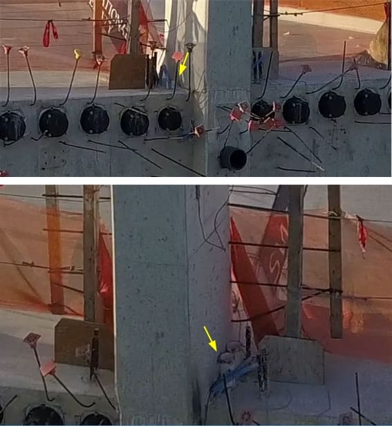
Main point of interest: the approach of #11 to #12, and to the deck. Note the "fillets" between #11 and #12, and between #11 and deck, which I had not previously noticed. A yellow arrow indicates white pipe with red tape or paint on rim that correlates to a later image.
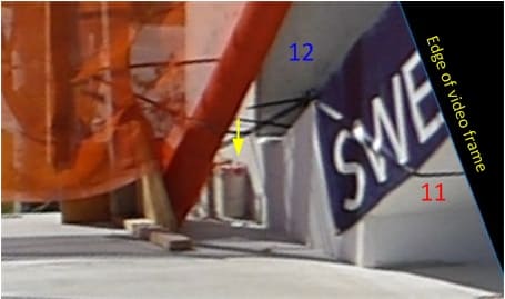
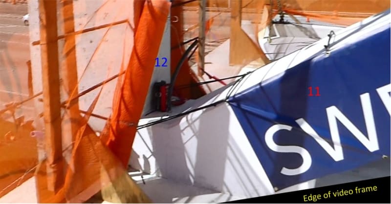
The area pictured above corresponds to the area captured from the NTSB B-roll footage, which I previously posted, wondering the function of the rods marked with yellow "?". These rods are enclosed in white plastic pipes; the one on the near side bears red tape/paint:
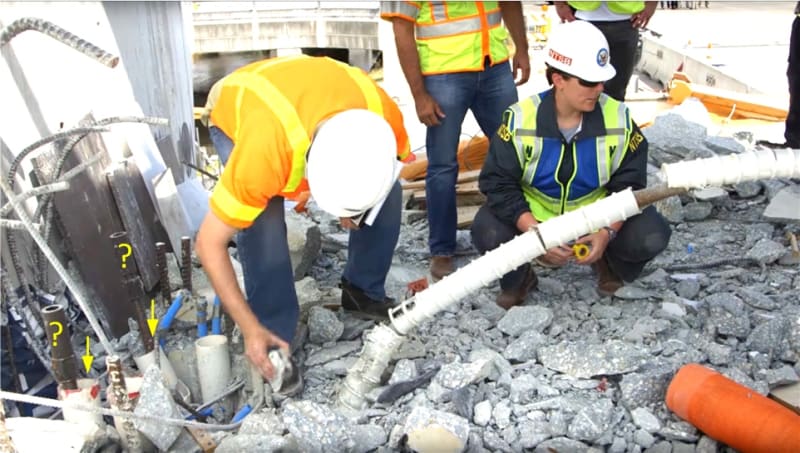
I had previously thought that these rods and their enclosing pipes were within the footprint of #12, but apparently, from pictures above and below, they are just outboard. I also thought that the other pipe on each side was perhaps part of services to be supplied up inside #12, perhaps along with additional channels in the void between the pipes. However, to me it now looks like the void between these pipes is simply where the base of #12 tore out at some stage in the collapse, leaving connecting rebar bent over to the extreme left of the picture.

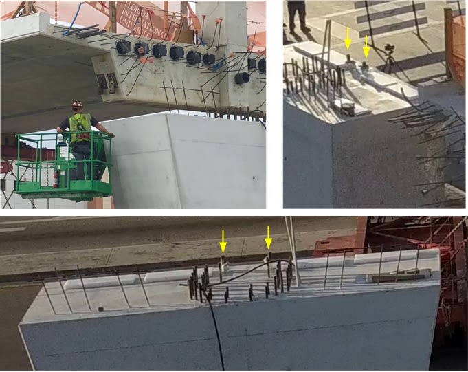
Steve Nuchia suggested these rods might be for position keeping. I think the following images show that the rods indeed tie the bridge to the pier, though they are not in the position shown on the proposal drawings, but have moved inboard. I'm thinking that the protrusions seen on the pier were extended in some way after positioning the span, so as to stick up through the deck's end-beam and out of the white pipes on each side of #12. These images are from drone footage during the move.

I imagine at some point we'll get to see photos of the cracks that were reported, and see whether they are in the 11-12-deck neighborhood.

RE: Miami Pedestrian Bridge, Part IV

@Ingenuity:

Thank you for your detailed response to my question in Thread #3.

When you look at the full picture of the member, putting things into terms of applied stress to the full section makes a lot of sense.

I think I was failing to wrap my head around this... as a mechanical guy who deals with a lot of HSS sections, I'm used to a 12" square member (just as an example) having a cross secitonal area of <<<< 144in2. Concrete is so different, even in little ways like that.

With that said- how do you account for transfer of all of that PT tendon load into the concrete so that the full section is developed?

The anchor for the PT tendon can't cover the entire section... is the anchor sized to keep the applied stress below some target value (based on concrete properties + design factors, etc), and then there is some stress distribution through the section as internal shear forces spread that load?

RE: Miami Pedestrian Bridge, Part IV

2
Member #12 damage overlap.

RE: Miami Pedestrian Bridge, Part IV

gwideman, excellent work with all the imagery.

RE: Miami Pedestrian Bridge, Part IV

gwideman:

Great...

Dik

RE: Miami Pedestrian Bridge, Part IV

Very interesting image + graphics by Meerkat 007.

I've now seen a couple of images that make it seem fairly certain that the junction of #12 at the canopy remained intact and rigid 90 degrees.
If that is the case, then the initial action would not have been crushing and shortening of #11, but rather the junction of #11 and #12 tearing out of the end of the deck, and thus 11, 12 plus the end of the canopy rotating as a more or less intact triangle. (For what it's worth, Alfie.Tx described this earlier while I was still favoring crushing and shortening of 11).

Meerkat 007's interesting stick model animation (22 Mar 18 12:04) with #11 missing, that compares well to the fuzzy slo mo dash cam video, has a couple of unsatisfactory aspects. It doesn't maintain a right angle at 12-canopy, and to make the geometry work out, the end support moves inward horizontally. If instead you have the 11-12 junction slide to the left (north), and maintain the 11-12-canopy triangle, at least initially, I think it works out better. That could match the dash cam video, since #12 is obscured from view by the crane.

Now once the triangle rotates a bit, and the collapse is underway, the canopy cracks between 12 and 11. The former upper end of #11 breaks due to rotation at 11-10-canopy, and is also crushed by the falling northmost segment of canopy. Meanwhile the former lower end of 11 (near 12), which is already damaged by the tear-out, smashes against the top of the pier. But 11 is partially maintained in its position in the triangle by its upper tension rod remaining connected at both ends.


RE: Miami Pedestrian Bridge, Part IV

Quote (gwideman)

the junction of #11 and #12 tearing out of the end of the deck

Best speculation so far. Very good. Once 11 failed to hold compression, 9 became end of the span stress wise and deck buckled there.

RE: Miami Pedestrian Bridge, Part IV

Quote (jrs87)

Best speculation so far. Very good.

Thanks, though again Alfie.Tx mentioned this earlier responding to an earlier post of mine (on top of all other preceding posts, including Ingenuity's thorough discussions of course!). At that time I thought an initial #11 crushing scenario seemed more plausible.

RE: Miami Pedestrian Bridge, Part IV

By the way Meerkat 007, I'd love to know how you constructed that graphic overlaying the #12 damage onto the intact bridge.

RE: Miami Pedestrian Bridge, Part IV

gwideman, Yes, I will be sure to recognize the input of others. Is the consensus now the PT rods and anchors in 11 did not fail, but rather the concrete or load distribution failed? Changing the PT rod tension moved compression/tension interface around near 11-12-deck in unforeseeable ways?

RE: Miami Pedestrian Bridge, Part IV

jrs87: Assume you mean "consensus"? I can only state my consensus with myself, which doesn't count for much, not being qualified in this field.

However, I am tempted to think that just by geometry, if the 12-canopy junction maintained its angle, that precludes the action starting with #11 shortening. But maybe concrete+steel is more flexible than I imagine.

As to why it happened during PT rod tensioning or detensioning, I don't have a comprehensive theory. For one thing we don't know where the PT end plates are.

We do know the lower tension rod was the one being adjusted, and it stayed with the deck. So if it was being tightened, then it would have increased the force pushing #11 out the end of the deck, I guess. Straw, camel, etc.

RE: Miami Pedestrian Bridge, Part IV

gwideman, Thanks, yes it was a typo. You may not be qualified in field, but you are a good thinker. I will take a rest from posting today. Look forward to reading for a day or so instead....

RE: Miami Pedestrian Bridge, Part IV

6
jrs87 got me thinking about why might tightening of the tension rod precipitate ejection of 11 and 12 from the end of the deck.

IF that occurred, here's a possible model:
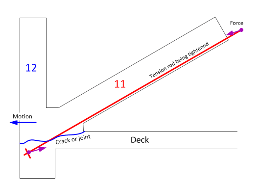


And we don't know whether they were performing an overall tensioning or de-tensioning operation, but as has been described earlier, even detensioning requires first some tensioning to loosen the nut. That small additional tension wouldn't explain why there's a crack in the first place, but it might explain why, given an existing crack or poor joint, the collapse occurred during the adjustment operation.

RE: Miami Pedestrian Bridge, Part IV

2
There appears to be a cold joint in 11-12 at the top of the deck. See photos above. If the PT rod(s) is anchored below that point, somewhere lower in the deck, and you increase the PT force, you increase the shear along the cold joint.

RE: Miami Pedestrian Bridge, Part IV

gwideman just beat me to it.

RE: Miami Pedestrian Bridge, Part IV

gwideman, your diagram does make sense, the lower PT bar did in fact stay with deck (it zippered out of 11), and the upper one stayed with 12 after collapse.

RE: Miami Pedestrian Bridge, Part IV

2

Quote (gwideman)

Quote (By the way Meerkat 007, I'd love to know how you constructed that graphic overlaying the #12 damage onto the intact bridge.)

I searched for images with reference points and angles in same plane and mixed with a software editor capable to work with layers and transparency, GIMP in my case.
Images used:


Confirmation for north end of deck:


No traces from end of #12 outside deck:

RE: Miami Pedestrian Bridge, Part IV

@Meerkat 007: Nice! Well done finding images with same orientation. I imagined you had some clever technique that rotated 2d images in 3d to get them to align.

RE: Miami Pedestrian Bridge, Part IV

...you computer guys/gals...us poor structurals still talk about (and some of us use) slide rules...fancy digital re-construction. Nice.

RE: Miami Pedestrian Bridge, Part IV

I am rethinking the shear surface. The skid marks and impact on the pier are along each side not in the center where the extension of member 12 would have impacted and slid. Perhaps the failure occurred through the white pipes with red on top. The photo of the NTSB worker digging through the rubble looks like there is a void between the two sets of white sleeves. The pipes would have made a weakened shear surface. Thoughts?

RE: Miami Pedestrian Bridge, Part IV

Quote (RetiredSE (Structural))

Concrete of member #12 base was pulverized before north deck end fall.
You can still see skid marks of like 2 rebars on pier surface.

RE: Miami Pedestrian Bridge, Part IV

Quote (RetiredSE)

I am rethinking the shear surface.
Yes, I had been thinking similarly, and yes those pipes/sleeves seem a weak area.
I wonder what apparatus was supposed to act against #11's horizontal force. What is visible in the ntsb picture is the set of vertical rebars to the extreme north (left) of the picture, that presumable were inside #12. Their other ends perhaps fold in an L-shape under 11, and extend horizontally southwards into the deck, perhaps for some length. The tension in those rebars would produce compression in the north end of the deck, resisted by the deck tendons. If that was the entire apparatus, and if the vertical portion of the "L" bars broke out of #12, then 11 and 12 move north.

RE: Miami Pedestrian Bridge, Part IV

Note the white pipe in deck is matched on canopy if I'm not mistaken. The bar couplers shown on NTSB deck photo connect bars up to canopy? The rebar (looks like tv antenna) on 12 may have been meant to tie 12 with other section simply to form hexagon shape shown in plans.

RE: Miami Pedestrian Bridge, Part IV

Quote (Meerkat 007)

Concrete of member #12 base was pulverized before north deck end fall.
Agreed.

RE: Miami Pedestrian Bridge, Part IV

I have taken the liberty of taking the Miami Herald video and breaking the order of construction down into 13 stages. These are screenshots from the video. For clarification every step is self evident with a couple of exceptions. Between stage 9 and 10 it is not clear to me if all of the web members were poured at stage 9 or if they were poured monolithically with the canopy in stage 10. This is important only from the point of view of where the cold joints probably are.

Stage 1 base for structure is completed
http://files.engineering.com/getfile.aspx?folder=a...
Stage 2 formwork for bottom flange completed
http://files.engineering.com/getfile.aspx?folder=e...
Stage 3 Vertical formwork for web members completed
http://files.engineering.com/getfile.aspx?folder=d...
Stage 4 sides of web members formed against vertical backing
http://files.engineering.com/getfile.aspx?folder=5...
Stage 5 PT ductwork and mild steel reinforcing placed in deck and web members
http://files.engineering.com/getfile.aspx?folder=c...
Stage 6 Bottom flange poured with cold joints near deck level in the diagonal members
http://files.engineering.com/getfile.aspx?folder=3...
Stage 7 Remainder of bottom flange poured
http://files.engineering.com/getfile.aspx?folder=e...
Stage 8 Diagonal front forms completed but not specific if web members are poured immediately leaving cold joints just below the canopy
http://files.engineering.com/getfile.aspx?folder=b...
Stage 9 Canopy is formed with PT ducts and mild reinforcing in place
http://files.engineering.com/getfile.aspx?folder=1...
Stage 10 Clear that the caps on diagonals have a cold joint at the deck and tops of diagonal members and caps to be poured separately
http://files.engineering.com/getfile.aspx?folder=c...
Stage 11 Caps over diagonals are poured
http://files.engineering.com/getfile.aspx?folder=0...
Stage 12 Equipment removed and presumably post tensioning took place.

Sequencing of PT probably Bottom flange then web members and then canopy but this is only speculation on my part.

Wanted to go through this step by step to 1) get an idea where cold joints might be in the web members to the deck an canopy and just clarify that the concrete was poured as a monolithic structure.

If someone knows how to have the photos as part of the post I would appreciate their input.


RE: Miami Pedestrian Bridge, Part IV

2
gwideman, given your assumed shear failure plane with the PT bar crossing it, tension in the bar would create shear friction, a clamping action tending to keep the two interfaces in contact. If the bar was detensioned, this would tend to reduce the shear friction and increase the likelihood of failure. Because the bar was in an ungrouted duct, the bar itself would offer little resistance to a shear failure, and given the other elements in the vicinity of the joint tending to reduce the effective area resisting shear, such as the 8" drain pipe and other ungrouted PT ducts, removing tension in the bar could cause failure.

I assume the bar was being detensioned because the PT was primarily required for the transport operation. Once the girder was seated on the pier, and compression introduced into member 11, the need for the PT, for the sake of strengthening member 11, would become unnecessary. We don't know if the hydraulic jack operator was just starting the detentioning process or was nearing its completion. It is possible that he was at the end of the detensioning process when the bridge failed.

Additional comment: There does not appear to be any actual joint reinforcement of the type one would find in a bridge designed to resist seismic forces. This type of reinforcement would have helped confine the concrete in this high stress zone, making it more ductile and less prone to a catastrophic failure. The innovative design, the lack of redundancy and the high stress concentration at the interface between the deck and diagonal would have made joint reinforcement a prudent choice. It would have added little to the cost of the design while providing a substantially more robust structure.

RE: Miami Pedestrian Bridge, Part IV

Just a general blood pressure warning - do not search YouTube for videos of people explaining this. I would suggest cat videos instead.

RE: Miami Pedestrian Bridge, Part IV

I agree with JRS87's posting/theory, "This bridge failed because deck separated from joint 11-12. Half the steel of 11 went with deck, the other half went with 12. Joint burst and beam zippered."

I have followed this disaster closely since I first saw pictures of the bridge on the news. The design immediately concerned me. It just looked too fragile with clear points of highly concentrated shear. I have read every comment on this thread and appreciate learning a lot from the community. At this point, I feel the design was inadequate and the bridge bound to fail. I share my assessment based on many years of practical operational and management experience. I am by no means a bridge or structural expert, I look forward to further discussion on this thread and to studying more expert and complete assessments as they are shared.

One point in support of this theory that I would highlight relates to the excellent time-lapse footage of the collapse from a dash-cam video created by Zac Doyle and linked earlier in this thread. https://www.youtube.com/watch?v=D6pGzgm4zZ4&fe... I've watched this video many times, trying to catch the first sign of failure. If one watches the left edge of the bridge, on the backside of member 12, opposite the 11-12 joint, a small bulge appears at 16/17 seconds. I believe this is the initial separation of joint 11-12 from the deck. Thanks to Meerkat 007 for first pointing out the small bulge and for first linking to this helpful video.

RE: Miami Pedestrian Bridge, Part IV

From the concrete pour sequence we know that at the ende of 11 and 12 there is a cold joint in the concrete near the deck (not great in shear) and not a lot of mild steel reinforcing to transfer shear - this joint in my opinion definitely failed and caused the collapse. Not enough normal reinforcing to result in a more elastic failure.

RE: Miami Pedestrian Bridge, Part IV

I think this video may answer appster's question: at 1:35 it looks like the members were poured before the canopy.

RE: Miami Pedestrian Bridge, Part IV

emba
Suspected that but now it appears to be confirmed. So still a cold joint at the top of the web members probably slightly below the joint with the canopy. If so this would be a weakened shear plane if no sufficient plain rebar and stirrups.

RE: Miami Pedestrian Bridge, Part IV


Most opinions are agreed on member 11 to be problematic.

The evidence in front of our eyes are the canopy (upper deck and top chord of the truss) and the walkway (lower deck and bottom chord of the truss) are still reasonable intact and in one piece. Some truss members could not be seen in the north half and some appear to have punch through the roof.

The important Member 11 actually is still intact and lied behind the folded canopy with the broke off end pointing upward after it has pulled/sheared off from the walkway which is resting on the ground. The PT duct has come off by breaking free all the stirrups (shear reinforcement).

The design drawing shows the walkway has been post-tension both longitudinally with 12 PT ducts and transversely with PT at 2' 6" centers. That explains it is still in one piece lying on the ground.

Thus the joint of member 11 has broken from the walkway which is 31ft wide acting as the bottom chord for a truss of only approximately 2ft wide. The first question to any designer is how much width of the walkway can successfully interact effectively with the middle truss. There are guidance in the codes for that.

Some serious reinforcement would be required to dissipate the force in the member 11 into the bottom and top chords of the truss?

The broken concrete of member 11 in the photos show only a few small diameter bars.

If the structure has been analyzed as a rigid frame, which I cannot see any other alternative, it is the designer's duty to make the joint rigid enough to transmit the shear forces and bending moments.

Due to the changes of transporter positions Member 11 was in tension due to one bay free hanging like a cantilever. It is possible that the designer mitigated this change by adding PT ducts, which were not listed in the original design drawings. When the bridge was supported finally on the two end abutments the axial force in Member 11 changed to compression so it would have been a need to adjust the bolts by tightening it.

The member 12 and its connected top chord canopy are redundant as the structure without them can still work like a standard Warren truss. The joint in the bottom of member 11 must be adequately restrained or it can shear outward to trigger a failure. The photos, provided by gwideman on earlier post on 21 Mar 18 04:50, of the fully exposed bottom end of Member 11 does not show evidence that the joint there has been adequately reinforced to dissipate the force, shear and bending.

It is possible that Member 11 and 12 became detached from the walkway during the collapse but the same photos show the top of Member 11 still attached to the top chord or canopy which has a much more robust joint arrangement. However the canopy folded just before the robust joint section.

The broken-off end of Member 11 has rebar I estimate mostly small diameters like 5/8" to 3/4" and does contain any transverse PT duct or tendon. The densely spaced 67 number of transverse PT casing has a concrete cover of 3.75". This could suggest the Member 11 could have shear off outward to the North with a layer of maximum 3.75" of the top concrete from the walkway. The downstand beam here is also only 2'10.5" wide. The south side, with a 3'6" downstand beam did not collapse and still have the canopy and walkway separated by middle truss after the collapse.

There is no code to help a designer on how much steel reinforcement to put in to dissipate the stress. It is down to experience and to realize the design assumption that the joints are rigid enough. When the reinforcement drawings are available a more definitive assessment could then be made.

The evidence so far points to the Member 11 wasn't adequately reinforced/connected to the 2'10.5" wide downstand beam and the walkway. May be the embedded longitudinal PT anchors were in the way but the designer must have a scheme to pass the axial tension (occurred during swingin-in) and then compression (in service) into the walkway because the truss system lies in the middle empty 3'1" corridor where there is no longitudinal PT system.

RE: Miami Pedestrian Bridge, Part IV

(OP)
Cold joints are inevitable. And you would not want to cast the inclined members with the canopy, as plastic settlement could result in a gap at the top of the web members. So sequence of placing concrete was correct. It was the design which was deficient.

RE: Miami Pedestrian Bridge, Part IV

From the photos above by Meerkat 007 and JRS87, damage to 12 base appears to extend nearly to mid-height! And in the "end on shot" of 12 there's a stub that extends from the base that is almost semicircular, as if the front side was pummeled, causing the weaker corner edges to be chipped away. It's hard for me to see how this could happen if the 11-12 base sheared off together as a unit at the construction joint/ deck surface.

RE: Miami Pedestrian Bridge, Part IV

TheGreenLama - on the III discussion board, 4Alfie.Tx posted a simulation that suggested that the 11-12 base indeed did not stay together, else member 12 would have been pushed to the north. Quote is below

"Meerkat007, your comparison between bridge collapse movie and theoretical simulation of truss without member #11 looks similar. It tells that the diagonal #11 crumbles at the base first, otherwise, it would have pushed out #12 a great distance based on the geometry as shown below, before the base slab tore away from #11 and #12."

RE: Miami Pedestrian Bridge, Part IV

Meerkat007 and jrs87 photos show the steel reinforcement of the broke-off end of Member 11 still firmly attached to Member 12. However no significant reinforcement is visible between these two members with the walkway which is supposed to work as the bottom chord of the truss.

The left-over of the Member 12, which is still on top of the pier, is a strong evidence the Member 12 have detached from the walkway by a horizontal force overcoming the shear capacity of the connection.

Meerkat007 has identified the bulge in the 17/19 seconds of the Zac Doyle Youtube video. This collaborates rather well with gwideman's shear failure sketch posted 23 Mar 18 17:09. When considering the positions of the longitudinal and transverse PT systems and comparing them with the photos it is possible the shear plane might have occurred at a slightly higher lever.

RE: Miami Pedestrian Bridge, Part IV

Regarding the concrete pour sequence.

1. I think the Miami Herald video referred to by appster is actually a computer animation, and may not reflect actual steel or actual concrete sequence. Correct me if I'm wrong.

2. What do we actually know about what was poured when? In the Stuart Grant video linked by rebardan, concrete trucks show up at about 1:33, and next day, or following day, forms are stripped and deck and vertical and diagonal members appear to be done, so that would mean the deck and the joints at the deck were poured more or less continuously. But I'm not really sure what I'm looking at in the video, nor whether the time lapse has had "non activity" edited out.

RE: Miami Pedestrian Bridge, Part IV

2
Does anybody know what tendons were specified for the bottom chord of the truss? They are type 5 specified on the drawings (meaning each cable is 13mm dia.) however it doesnt specify how many cables per tendon there are.

** Edit, I have updated the check below to show the 0.6" x 19 cables per tendon which was found in earlier thread and brought to my attention by username Ingenuity this is numerical proof now of where the failure is and why it failed**

***Case Closed***


RE: Miami Pedestrian Bridge, Part IV

gwideman - what is happening between 1:24 and 1:25? I thought that could be the deck pour but I also am not really sure what I'm looking at.

RE: Miami Pedestrian Bridge, Part IV

Sorry, not sure if I was clear on my previous post, my hypothesis is as follows:

- Insufficient development of bottom chord reinforcement at the node of member 11 and 12 junction.

- This is further made worse by the drain pipe punching through this junction as well as grout ducts/tubes either side of member 12 at this node. This reduces the shear plane area and makes it harder to engage the PT tendons that are quite some distance away from the node itself.

- The node detail is made even worse by the fact that the end face of the bottom deck doesn’t actually continue all the way to the outside face of member 12, making development of the PT cables where it is required even more problematic. This means we are engaging very few of the cables in reality at the node.

I’ve completed a few rough hand calculations to verify the loading and forces we are dealing with. I am old school and believe that we don’t need FEA or fancy analysis to solve such a simple determinate system.

My biggest surprise is the media didnt overfblow the bridge weight to make the story more interesting, the bridge does in-fact apear to be circa 900-990 tonne of self weight.


RE: Miami Pedestrian Bridge, Part IV

Timed the collapse, took a little under half a second from the first suspicious event before the structure visibly bends. The first frame is where I was able to pick up a batch of pixels that resembled the concrete protruding from the bridge. The debris seems to blow out at least 5-6 feet at the 1/3 second mark before the bridge comes down.

RE: Miami Pedestrian Bridge, Part IV

Quote (SheerForceEng)

Does anybody know what tendons were specified for the bottom chord of the truss? They are type 5 specified on the drawings (meaning each cable is 13mm dia.) however it doesnt specify how many cables per tendon there are.

Yes, the PT has been summarized in previous parts. See thread815-436595: Miami Pedestrian Bridge, Part I and go to post with time:date stamp of 17 Mar 18 07:27

RE: Miami Pedestrian Bridge, Part IV

Quote (ingenuity)

Yes, the PT has been summarized in previous parts. See thread815-436595: Miami Pedestrian Bridge, Part I: Miami Pedestrian Bridge, Part I and go to post with time:date stamp of 17 Mar 18 07:27

Thanks for this, I have updated above, it shows it pretty conclusively now.

I have used some data from this forum as well to help with the numbers so thanks to everyone for contributing.

Cheers,

RE: Miami Pedestrian Bridge, Part IV

Quote (saikee119)

Meerkat007 and jrs87 photos show the steel reinforcement of the broke-off end of Member 11 still firmly attached to Member 12. However no significant reinforcement is visible between these two members with the walkway which is supposed to work as the bottom chord of the truss.

I see the reinforcement of 11 as entwined with 12, not firmly attached, and it is entwined higher up 12 than its original location.

And in the 4 screen grabs by INCENTIVE immediately above, member 12 looks to remain in the vertical position for the first 3, well after the postulated debris is blown out of the end.

And in one of the earliest posted videos by Tomfh in Thread I, 18 Mar 2:42, member 12 actually looks, of all things, to be pulled inwards. Of course its final resting place is on top of the pier, so 11 would have to push it out in the final moments.

RE: Miami Pedestrian Bridge, Part IV

Previous posts in PART I, II and III of this subject have asked about previous prestressed concrete truss bridges.

I was recently browsing through a book "200 Years of Concrete In Australia" and came across this construction photo of the RIP Bridge (no it is not an acronym of R.I.P). It is a prestressed concrete truss, located on the waters of Woy Woy, about 100 km north of Sydney. Constructed in 1974. Main center span of 183 m (600 ft) and a total length of 330 m (1080 ft):


If I recall correctly, it "suffers" from excessive upward deflections at the center. During the period of when free cantilever bridge construction was in its infancy, several bridges experienced excessive creep deflection, with noticeable mid span sag (downwards displacement), so additional prestress was applied to avoid any sag - unfortunately too much prestress was applied to the RIP Bridge, and 'creep' - acting opposite to gravity effects - caused its midspan 'hump'.

RE: Miami Pedestrian Bridge, Part IV

2

Quote (SheerForceEng)

***Case Closed***

We will inform the NTSB. They will send you a check. US$ okay? smile Aussie sarcasm - dies hard!

RE: Miami Pedestrian Bridge, Part IV

SheerForceEng
As I pointed out in Part II shear lag is a definite design consideration in this structure particularly at each end. The ducts in the deck are plastic even though I feel they should be metal to make the bond more secure for the grouted strands; there is no lateral distribution reinforcing of any consequence near the strand terminations and the lateral deck tendons are at 2'-6" oc. If your theory is correct then the structure should have failed at the opposite end where member 2 is at an even flatter slope. Are there fewer service ducts and post tensioning ducts at the other end reducing the effective bond and local area of concrete.

Not sure but lateral distribution of loads from the web to the flanges is definitely an issue and could be a factor in the failure. As per Ingenuity I would not cash the cheque yet, case to me is still open.

RE: Miami Pedestrian Bridge, Part IV

Quote (appster)

If your theory is correct then the structure should have failed at the opposite end where member 2 is at an even flatter slop

Because the trigger is destressing the temp PT bars in member 11 If destressing didnt occur at the other end yet then it will still have the PT tension bar artificially holding the node together.

Quote (ingenuity)

Aussie sarcasm - dies hard!

I get it mate Im Aussie!!!!!

RE: Miami Pedestrian Bridge, Part IV

They announced that de-tensioning had been completed at the other end and one rod on the North; were working on the last bar when the failure occurred.

RE: Miami Pedestrian Bridge, Part IV

Re: SheerForceEng (Structural)24 Mar 18 01:32

Very good post, I agree. As to FEA, I would not be surprised if NTSB builds a physical copy of 12-11-deck portion in their lab.

The the end-on photo of 12, I see a faint sign of a large perpendicular bore hole in fracture.

Does anyone know what deck rested on? In photos I see what appears to be 4 nylon bearings at top of pylon pier. Are these spaced in such a way 11 can punch through deck? I don't know.

RE: Miami Pedestrian Bridge, Part IV

Quote (INCENTIVE)

(Dashcam frame-by-frame)
Off the left end I see a few pixels of something. More conspicuously, I see a more solid object progressively protruding to the left at deck level, which it's tempting to see as 11-12 pushing out to the left, maximum at 00.00.38. However, it could also just be that "protrusion" is really just the north-west corner of the deck and changing perspective as the vehicle and camera move toward the bridge. Someone on an earlier part of this thread discussed this too, I don't recall the conclusion. Unfortunately that area is behind what I believe is a cherry picker arm, so difficult to see the continuous visual lines of the deck.

RE: Miami Pedestrian Bridge, Part IV

Quote (appster)

They announced that de-tensioning had been completed at the other end and one rod on the North; were working on the last bar when the failure occurred.

You will notice at the other end of the bridge the bottom deck continues all the way to the outside far face of the vertical member giving more concrete pull out capacity as well as engaging potentially more PT tendons in the process. This would explain potentially.


RE: Miami Pedestrian Bridge, Part IV

I have felt for some time that there might be other detail differences at the ends which saved the South end from failing first, or there was some difference in the PT stress or procedure at each end. Voids in the concrete due to compaction differences or areas being affected by ducts or drains may also be different.

Shadows shown in the progressive collapse shots indicate that it was a bright sunny day, the cars are not casting long shadows east or west so the the sun is almost straight up; the canopy would therefore be at a higher average temperature than the web or bottom flange adding some added thrust to the end diagonals as it tries to expand. De-tensioning of 2 was carried out earlier in the day when the temperature was cooler and the canopy not shading the web so effectively.

A later post indicates that the depth of member 2 was increased leading to a much longer footprint for 2 meeting the deck at such a flat angle. This longer footprint gives more shear area at the deck to transfer its compression load into the deck and also brings more tension strands in the deck into effect in resisting the tension in the deck from the compression in 2. Major difference between North and South end to explain why south end did not fail first.


RE: Miami Pedestrian Bridge, Part IV

Quote (pontduvin)

tension in the bar would create shear friction, a clamping action tending to keep the two interfaces in contact. If the bar was detensioned, this would tend to reduce the shear friction and increase the likelihood of failure.
That thought crossed my mind too, especially that loosening could precipitate the failure. But much depends on the positioning of the PT rod endplate, the angle relative to the crack/joint, etc. My sketch was only meant to illustrate the idea that changes on the PT rod could be somehow correlate to the time of failure. Likely the endplate and the crack/joint would not be exactly where I showed, especially of #12 got pushed out right to its bottom.

RE: Miami Pedestrian Bridge, Part IV

Quote (jrs87)

I would not be surprised if NTSB builds a physical copy of 12-11-deck portion in their lab.

From NTSB website: Link

Quote (NTSB)

While segments of the bridge are being transported to and stored at an FDOT facility, there are no plans to reconstruct the bridge as part of the NTSB investigation into why the bridge collapsed. The nature of the structure and the way it failed make reconstruction impractical.

Although the NTSB state "no plans to reconstruct the bridge" this does not rule out a small scale joint segment for testing...but I doubt they will. Time will tell.

RE: Miami Pedestrian Bridge, Part IV

Quote (Ingenuity)

Quote (jrs87) I would not be surprised if NTSB builds a physical copy of 12-11-deck portion in their lab.

Would I be right in thinking that an early NTSB task would be to identify whether the fault lies primarily in the (computer) model, or in the physical construction? I'm thinking that NTSB can presumably get hold of the model that FIGG used, and test it using same or different software, applying a creative range of test conditions to identify vulnerabilities etc. Is that a relatively quick and low-investment task?

RE: Miami Pedestrian Bridge, Part IV

Some excellent theorising here and well done to all those keeping this on an engineering level backed up by good graphics and use of photos.

My take now is definitely moving towards movement of some sort of the base of 11/12 being the root start point, but less than 0.5 seconds is brutal to determine cause and effect. Given that this was essentially a rigid structure, even a small movement of column 11 ( 10,20,30mm??) would surely lead to a large movement of loads onto other parts of the structure not designed for it, leading to failure. The key part for me was realising that the top tendon in column 11 is intact and clearly anchored into the base of column 12 and survived more or less intact. The lower tendon which ripped out of no 11 was anchored into the slab somehow and hence tension on it was providing some of the anchoring / shear resistance to the base of 11/12 as postulated above. Once the tension was released a bit it transferred load onto other reinforcement / tendons which couldn't cope.

One thing maybe to throw into the debate is whether as the bottom tendon in no 11 was released as we believe it was or could be, this then would add to the load on the inner two tendons in the base slab as noted by sheerforeceeng. Could the item seen on the left of the video screen grabs by ingenuity actually be one or both of those inner tendons breaking off? Remember at the start that prior to the collapse, some "twanging / bull whip cracking" noise were heard by a member of the public as he went underneath he structure waiting for the stop light. Was that one of the strands in an over worked tendon snapping?

We have no visibility of the end of the bottom slab at that point as it collapsed right next to the pillar so until it is lifted out of the way no way to say what the end of the bottom slab looks like and if all the tendon ends are still there.

The release of facts in the next couple of weeks hopefully by the NTSB will be very interesting.

Remember - More details = better answers
Also: If you get a response it's polite to respond to it.

RE: Miami Pedestrian Bridge, Part IV

Tension adjustment in No. 11

In the design drawings the collapsed bridge was supposed to be shifted by 4 transporters, 2 for each end. The two transporters at each end support the end bay. Thus No. 11 in the original design would have little load and only in compression. No PT was listed in the drawing.

In actual execution the end transporter was proved to be impractical and was shifted to the interior span. So the last bay at each end was free hanging and so No 11 would have to take 1/5 of the 950 tons dead weight (5 bays) and resisted pure tension.

It is possible that the PT was introduced to resist this changed condition.

Once in final position No. 11 would be in its highest compression and the tension in the PT is no longer required.

Logically the forces in the two PT ducts should be removed. Exactly how the tensile force, introduced in the construction sequence, was dealt with is not known to us yet. However if the tendons were tightened even slightly when No. 11 is already fully compressed a small axial shortening has to take place. The top canopy and the bottom walkway will have to be bent inward. This can initiate the failure of the connection at the bottom of No. 11 and 12 if it the point of the least resistance.

RE: Miami Pedestrian Bridge, Part IV

Quote (TheGreenLama)

And in one of the earliest posted videos by Tomfh in Thread I, 18 Mar 2:42, member 12 actually looks, of all things, to be pulled inwards.

I think there may be some confusion over the motion of #12 because behind #12 there is a tree. As the vehicle and camera moves, due to changing perspective the tree moves rightward relative to #12 in the foreground, possibly making it look like #12 itself is moving.

Here's a frame from earlier in that video: https://youtu.be/Ucflj-MsJBI?t=4 , in which the tree in question can be seen to the left of #12.


RE: Miami Pedestrian Bridge, Part IV

That computer animation showing the assembly of the FIU pedestrian bridge (Miami Herald) explained my question about how the transporter was positioned under the finished structure.

RE: Miami Pedestrian Bridge, Part IV

Quote (Ingenuity)

Previous posts in PART I, II and III of this subject have asked about previous prestressed concrete truss bridges.

About 40 or so years back, I was at a presentation of a couple of new bridges under construction in Germany; one of them was the Bendorf Bridge, and, I don't recall the name of the second one. they were both post-tensioned using Dywidag threadbars... Rebar's cheap, but, the connectors aren't. One bridge went across a gorge and was supported on columns/piers that were several hundred feet high. Both were constructed using the 'backspan' to support 'flying' construction equipment. That's when I started using Dywidag for seriously loaded anchorage.

Dik

RE: Miami Pedestrian Bridge, Part IV

Regarding 11-12-deck, I wonder if a structural engineer might comment on how such joint systems work typically? What they might expect to see inside this bridge?

The ongoing discussion leads me and some other posters above to wonder how the design intends to route stress from #11 to the deck's tendons. For orientation, we're discussing this area:


A naive first speculation might be like the picture (plan view) below, which troubles the mind because of its poor distribution of forces to the tendons. (I think SheerForceEng remarked on this):


So perhaps the idea is like in the following image: #11 presses on the deck end beam, which in turn acts as (or contains) a very stiff bar distributing the horizontal load to the tendons. Is that feasible?


Or might the horizontal load from #11 be constrained by rebar that folds back south (rightward) into the deck for some distance: Either rebar in #11 folding like a hairpin under #11 into the deck, or L-shape rebar, with one leg vertical in #12, and a horizontal leg into the deck. Those horizontal legs in the deck could be long enough to spread compression broadly into the deck, to be resisted by the tendons?


Might this last scheme, if a valid approach, correspond to the rebar seen at the left of the NTSB "rubble" photo earlier on this page, apparently torn out of #12?

RE: Miami Pedestrian Bridge, Part IV

Great schematics!

If shear failure at the ends of the structure was the cause, it seems that an approach more towards a solid web of the I-beam by both ends could have added some safety factor with little penalty regarding materials, weight and "aesthetics".

For example, another horizontal beam resting on the lower deck, with horizontal PT elements running between the low portion of the two last diagonal members of the web.
In other words, forming a self-supported triangle that liberates the end of the lower deck from additional tension and shear loads, as well as those diagonal members and their nodes from bending loads (element 10-horizontal beam-element 11 and element 2-horizontal beam-element 3 triangles).

"Where the spirit does not work with the hand, there is no art." - Leonardo da Vinci

RE: Miami Pedestrian Bridge, Part IV

appster - differing from the preliminary plans, the as-built bridge approximately doubled the depth of member #2.

See the post by SomewhereOverChina (Electrical)22 Mar 18 03:32 on http://www.eng-tips.com/viewthread.cfm?qid=436802

His example photo:

RE: Miami Pedestrian Bridge, Part IV

2
Regarding the protrusion at the left end of the deck, shown in the time-lapse video right before the failure initiated, I think gwideman is correct, it is just the deck corner coming into view as the position of the camera continually changes position.

We know that lower PT bar in member 11 crossed the failure plane at the end of the deck because its anchorage remained in the deck section after the collapse, causing the bar to be ripped out of member 11 as it fell. This supports the theory that the horizontal failure plane was located somewhere near to that shown in gwideman's sketch.

It also appears that the deck section remained nearly intact after the collapse. This seems to imply that the longitudinal post-tensioning in the deck did not adequately participate in transferring the compression in member 11 to the deck.

The failure resembles a punching shear failure in a pile supported footing with no pile under the column, only in this case the column was at the edge of the footing. The only benefit of member 12, and the future pylon, in resisting shear failure, other than a bit of confining compression pressure on the joint, is that they necessitated the need for vertical mild reinforcement through the failure plane. But the contribution of this steel would be minimal until the bridge was completed.

It is unfortunate that a longitudinal PT strand was not positioned to run down the middle of the deck as this would have directly resisted the punching shear of number 11 transferring the load directly to the deck by confining the end of the girder with a PT anchorage plate. The location of the 8" deck drain may have prevented this...an unfortunate tail wagging the dog effect. This drain pipe also seems to have dictated the temporary bearing locations on top of the pier preventing a reaction point directly under member 11.

The devil is indeed in details, especially in a modern concrete bridge where member sizes are minimized using PT to reduce weight, and aesthetics drives compromises in the placement of structural elements. The deck section was relatively thin given the localized demand placed on it by member 11 at this stage of the construction.

Once completed this bridge failure most likely would not have happened, so the accelerated staged construction can be said to have played some role in the collapse, though this only points to the need to carefully analyze each construction stage to ensure life safety.

RE: Miami Pedestrian Bridge, Part IV

Any idea of why the top of this bridge was coloured with a dark blue? It's not visible from anywhere, except the air, and maybe adjacent tall buildings. White would be less likely to 'heat up' on sunny days.

Dik

RE: Miami Pedestrian Bridge, Part IV

Dik, that's just shadowing due to the depressed pan shape of the top chord at night. Other photos above show the surface was the same light-colored concrete as the rest of the bridge.

RE: Miami Pedestrian Bridge, Part IV

Thanks, gentlemen... Just noticed it on the picture posted above.

Dik

RE: Miami Pedestrian Bridge, Part IV

Quote (Pontduvin)

It is unfortunate that a longitudinal PT strand was not positioned to run down the middle of the deck as this would have directly resisted the punching shear of number 11 transferring the load directly to the deck by confining the end of the girder with a PT anchorage plate. The location of the 8" deck drain may have prevented this...an unfortunate tail wagging the dog effect. This drain pipe also seems to have dictated the temporary bearing locations on top of the pier preventing a reaction point directly under member 11.

What would be the reason for the debilitating central location of the deck drain pipe, right on the plane of the web?

Is there any reason for the pitch of the deck not to drain towards both edges of the deck and then to collect the water by a low curb next to each edge and channel it out through two longitudinal pipes of smaller diameter, not interfering with the structural steel and PT cables?

Probably hard to get the proper pitch of any pipe in order to effectively and quickly drain at each end of this bridge if considerable span deflection existed.
If so, some accumulation of water could happen midspan, increasing weight on the deck.
This designed inward pitch could potentially add a considerable amount of water weight on the deck in case of drain clogging or hurricane type precipitation.

"Where the spirit does not work with the hand, there is no art." - Leonardo da Vinci

RE: Miami Pedestrian Bridge, Part IV

Take a look at the opp end. #2 appears to be a deeper member. Dashcam vid proves it took a licking and kept on ticking. In the prelim dwgs, it is same cs area as all the others. So, it appears someone ran the numbers again and decided to increase the area of #2 and not #11.

RE: Miami Pedestrian Bridge, Part IV

Quote (appster)

If your theory is correct then the structure should have failed at the opposite end where member 2 is at an even flatter slope.

If the preliminary drawing is accurate, unlike member 11, web member 2 (type B) was specified to have two permanent tensioner bars loaded at 200 KIPS each (please, refer to SheerForceEnd's post of 24 Mar 18 01:10 above).
To resist buckling under gravity of the more slender and horizontal member 2 perhaps?

That was specified prior the adjustments for transporting the structure while both ends where protuding beyond the jacks were made.
Those adjustments for temporarily resisting the negative moments (compression at the bottom of the I-beam and tension on the top) at both ends could have been adding two new tensioned rods to member 11 and increasing tension above the specified 200 KIPS in rods of member 2.

If that is true, tension for member 2 could have been only reduced, but keeping the specified values, which could have helped keeping the integrity of the lower node (end of slab, diagonal member 2, column 1) under shear and bending loads.
Perhaps the opposite end of the bridge (by member 11 and column 12) did not have that structural advantage if the directions were to release all the tension in both bars.

"Where the spirit does not work with the hand, there is no art." - Leonardo da Vinci

RE: Miami Pedestrian Bridge, Part IV

From the dashcam video, it appears the main deck failed first, at a point midway between the two verticals. Not at the 11-12 beams themselves, nor at the node where they intersected. The outboard (short section) then tilted (pivoted) down to the roadway with its nodes intact, but the rest of the bridge deck than fell nearly straight down.

As an aside, it is still not clear how the designers intended to drain that "bathtub" in the top of the cover. The center is high, so separate independent drains would be needed on both sides, but out there even white plastic pipes would be eyesores on this "architectural wonder" ...

RE: Miami Pedestrian Bridge, Part IV

racookpe:
I have been looking closely at the various photos and somewhat agree with you.
Consider:
Did member 11 fail due to crushing near the connection with member 11.
A crush failure would allow the member to effectively shorten and lead to the failure of the deck.
A crush of a portion of member 11 may account for the burst of dust seen behind member 12 immediately prior to the collapse.
Although the end of member 11 may have crumbled, effectively shortening it, it may have retained enough length and strength to hold the bottom of member 12 on top of the support as the main deck fell.
The damage to the bottom of member 12 may be consistent with the main deck falling away and breaking free from the support.
The rebar from member 11 and member 12 look to be running to the top of the support.
Once the 11-12 connection broke away from the main deck there is little save gravity to hold them on top of the support.
The damage may be consistent with the top of member 12 being restrained by the top canopy and the bottom of member 12 being restrained by the remnant of member 11 as the main deck fell and rotated away.
Note also that the end of the PT rod embedded in member 11 is still attached to the deck.
If the broken end of member 11 was supported by the support column and rebar connecting member 12 while the deck fell away with the end of the PT rod still attached, that would explain the PT rod "zippering" out of member 11.
Surely the connection between members 11 and 12 and the deck was much stronger than the connection between the 11-12 connection and the deck.
If the deck rotated away while the bottom of member 12 was somewhat supported by the remnant of member 11 the damage and final position of the various members may be explained.

Bill
--------------------
"Why not the best?"
Jimmy Carter

RE: Miami Pedestrian Bridge, Part IV

Alternately; The pinging noise reported may have been a failure of a PT tendon in the main deck prior to complete failure.

Bill
--------------------
"Why not the best?"
Jimmy Carter

RE: Miami Pedestrian Bridge, Part IV

Gwideman...your picture


As mentioned in my last post...the area you have blocked out in blue...there is a square block of concrete gone in the top section of the deck. The pipe 2 on each side of member 11 have not been grouted. It looks like 11 sheared and punched out a square. This is punching shear except it is in the horizontal plane not the vertical. This piece of concrete is what we see in Meerkat 007 video at 0:17 seconds protrude out horizontally in line with the deck.

RE: Miami Pedestrian Bridge, Part IV

waross:

If member 11 crushed (implying it was under excess compression forces for its cross-sectional area for that time of concrete curing), the entire lower deck was almost certainly under tension before any other event happened - because the bridge was supported only at the two extreme ends.
The upper canopy was under some compression - but the actual compression stress in the canopy varied between each member and between each node since the intersection angles varied at every node, and the distances between every node varied as well. Since some of the angled members were in great relative compression, and some in mid-compression (compared to the average member), could some members have been in tension?

RE: Miami Pedestrian Bridge, Part IV

...was just thinking... this almost looks like a 'big' strut and tie system...

Dik

RE: Miami Pedestrian Bridge, Part IV

3
From the April 2015 FIU-UniversityCity Prosperity Project - Pedestrian Bridge (page 13):

Quote (FIU-Pedestrian-Bridge-Design-Criteria-2015-05-06_REV.pdf)

5.9 Deck Systems
The bridge superstructure should be primarily structural steel with concrete walking surface. The design should avoid use of non-redundant, fracture critical members.

https://facilities.fiu.edu/projects/BT_904/FIU-Ped...

RE: Miami Pedestrian Bridge, Part IV

IEG:

Missed the fine print...

Dik

RE: Miami Pedestrian Bridge, Part IV

Where are the rebar linking No. 11 and 12 with the walkway?

The following photos were provided by gwideman on 23 Mar 18 10:54

They depict the locations of four plastic ducts, two on each side of No 12, before the collapse.


After the collapse gwideman showed the walkway deck with rubbles. The deck rest on the ground and tight against the abutment wall after the collapse.


The four plastic ducts are now visible but No. 12 member has gone. The long PT duct shown belong to No. 11. Thus the original footprint of No. 12 and 11 on the deck is in the above photo.
VolsCE84 has drawn the positions of No. 12 & 11 but his diagram appears too large and covers the 4 plastic ducts.

Do we not expect some reinforcement linking the No. 11 & 12 with the deck? The short vertical steel bars were started bar cast outside the No. 11 & 12 according to the first two gwideman photos.

I found it disturbing that no significant reinforcing bar from No. 11 & 12 embedded in the walkway deck. Anyone care to comment?

RE: Miami Pedestrian Bridge, Part IV

I wonder what impact this will have on the next bridge, and, whether it will be placed in the same location...

Dik

RE: Miami Pedestrian Bridge, Part IV

IEGeezer,

I believe the "FIU-Pedestrian-Bridge-Design-Criteria-2015-05-06_REV" is just a wish list of the Owner FIU. The Owner selected MCM/Figg's offer, accepted the contractor's design and awarded the contract.

It is also difficult to say the bridge superstructure isn't primarily structural steel because the finished product is similar to a cable stayed bridge except those who can read the design know the primary strength comes from the post-tension bridge. The final bridge isn't hang by cables but 16" diameter steel pipes.

The steel pipes can carry a significant amount if not the full load. Their main benefit, acting as spring supports in the interior points, is to raise the fundamental frequency of the footbridge to avoid resonance by the pedestrian traffic. They are also acting as redundancies for the structural system.

RE: Miami Pedestrian Bridge, Part IV

Quote (gwideman)

Regarding 11-12-deck, I wonder if a structural engineer might comment on how such joint systems work typically? What they might expect to see inside this bridge?

Ok, sure, I'm a Structural Engineer, see right at the very bottom for my solution and what I would expect for the joint detailing.

Quote (gwideman)

So perhaps the idea is like in the following image: #11 presses on the deck end beam, which in turn acts as (or contains) a very stiff bar distributing the horizontal load to the tendons. Is that feasible?

Quote (gwideman)

Or might the horizontal load from #11 be constrained by rebar that folds back south (rightward) into the deck for some distance: Either rebar in #11 folding like a hairpin under #11 into the deck, or L-shape rebar, with one leg vertical in #12, and a horizontal leg into the deck. Those horizontal legs in the deck could be long enough to spread compression broadly into the deck, to be resisted by the tendons?

Please see under for my comments on your schematics.

Bare in mind that according to my numbers, we only need one more 0.6"x19 Tendon running straight through the middle for the joint to work.


RE: Miami Pedestrian Bridge, Part IV

Quote (saikee119)

The steel pipes can carry a significant amount if not the full load. Their main benefit, acting as spring supports in the interior points, is to raise the fundamental frequency of the footbridge to avoid resonance by the pedestrian traffic. They are also acting as redundancies for the structural system.

You are correct on almost all counts. Redundancy however may be questionable. I agree that the CHS sections "can" take significant loading, but again the weak point is the connection which is a post-fixed bolted connection to the concrete top deck and the pylon. If the bridge wants to come down, with the cables attached with this detail, the CHS sections won't stop the bridge from coming down.

It also raises an interesting further question. I would assume that the design engineer would want these CHS sections to be attached as late as possible in order for the bridge to move and deflect as much as it can before the CHS's are fixed so they don't attract any unwanted loading that the connections may not have been designed for. Considering that the long term deflections of the bridge will continue well after the construction team is finished on-site, I'm wondering how the connections would have fared in the long run as they are forced to take more and more load with time as the bridge relaxes under creep and shrinkage.

As stated above, this would not pose a life safety issue at all however would begin to alter the frequency characteristics of the stucture and may begin to perform inadequately under vibration excited by foot traffic as the connections begin to yield.

RE: Miami Pedestrian Bridge, Part IV

I believe that the picture of the bottom deck in Incentives post above clearly shows that the tendons in the deck or the deck itself did not blow "out the back" but that section 11 and 12 sheared cleanly off at the deck due to inadequate shear capacity. Reliance mainly on shear in plain concrete with moments, torsional shear, possible added shear from temperature effects and near the location of a cold joint, just plain folly in my opinion. Shear lag in the deck would also be a factor here and apparent lack of PT tendon across the deck near the anchorage to help confine the deck concrete. Big thing is that 11 itself appears to have only nominal stirrups which would not give 11 itself adequate shear capacity. It could well be that 11 also did not have adequate moment capacity in both axes.

RE: Miami Pedestrian Bridge, Part IV

Quote (INCENTIVE)

Is it the consensus that the concrete seen protruding half a second before the collapse is just the camera angle/illusion? https://www.youtube.com/watch?v=D6pGzgm4zZ4

In my opinion it would be extremely hard to critique the failure mode of the bridge using the video footage alone, considering the footage was taken so far away.

Deflections and yielding of only 10mm would be enough to start a collapse of such a structure given that if is a truss and is not designed to bend primarily.

I don't believe the investigators would use the footage as a large percentage of support evidence in their findings, just to back up theories. At the end of the day, everything should (and can) be proved theoretically given the as-built drawings and an engineering analysis. I must stress again that this is not a complex sturcture and indeed a truss is something we all learn in Engineering 101 at university. Someone indicated previously that "months of analysis" would be needed to check these things, this is simply not the case. Engineers are not scientists/chemists, we like things to be simple, simple to build and simple to analyse. I am relatively comfortable with my pen and paper appraisal which took me 15 minutes to scribble to determine that there is a potential problem with the support node at junction 11/12.

There were questions about ductility and no warning given before the collapse earlier in these threads. Unfortunately the failure mode that I have speculated on earlier with my pen and paper hand calculations is not a ductile failure. If the PT cables weren't adequately developed or anchored near the support node, then this is brittle concrete failure as it shears out the edge of the bottom deck, litte/no warning will be given. Unfortunately this is unavoidable and codes around the world don't adequately address this, it's something we as design engineers have to deal with, much like punching shear failure can be brittle in nature as well.


RE: Miami Pedestrian Bridge, Part IV

RE: Miami Pedestrian Bridge, Part IV


SheerForceEng,

Re-examining the drawings I tend to agree with you that congestion will be a problem if the designer details some rebar from No. 11 to pass the stress into the deck. The transverse and longitudinal PT systems effective form barriers difficult if not impossible to thread through large diameter rebar.

Apart from using the drainage pipe position to add an additional PT line which will certainly help the situation. An alternative is to pass the rebar from No. 11 into the downstand section which some call end beam that has a beefy dimension of about 18'2" long by 4'2" deep by 2'10" wide. The end beam embeds all the longitudinal PT anchors below which there is ample space to bond reinforcement from the No. 11 to develop their full strength.

Another alternative is to weld a piece steel plate to say two sets of anchor PT plates on either side. The steel plate has to be at least same thickness or thicker than the PT anchor plate. If No 11 shear outward they have to take out at least 4 sets of PT tendons. To avoid bending the additional plate needs stiffeners which can be embedded inside No. 12.

The vertical member No. 12 can also be made strongly connected to the end beam to form an effective restraint or buttress.

I believe as an engineer we could all find different solutions to make a stronger connection for No. 11 & 12. The question now is has this connection been adequately designed or not overlooked.

RE: Miami Pedestrian Bridge, Part IV

Quote (sheerforceeng)

but again the weak point is the connection which is a post-fixed bolted connection to the concrete top deck and the pylon

I don't know how they were to be fastened, even through bolting to the plate on the other side... maybe we'll never know...

8 - 1-1/2" dia bolts are 'serious' attachment, depending on the grade of steel, capable of providing an attachment resistance of 400K or more. As I've noted before, the 'cable stays' are a bit of an enigma, they are supposed to be decorative, but offer substantial resistance. It would be a challenge to determine how the walkway would have functioned with them.

Dik

RE: Miami Pedestrian Bridge, Part IV

SheerForceEng,

I agree that the 8x1.375" diameter bolt connection for the stayed 16" diameter pipe is inadequate to realize the full strength of the pipe. My guess is this may be deliberately arranged as if the stayed pipes were fully load bearing the pylon will be bent due to the north side not symmetrical to the south side.

If the bridge is self-standing the tension in the pipes will not matter much to the overall deflection as the bridge will be much stiffer while the steel pipes will behave like soft springs.

RE: Miami Pedestrian Bridge, Part IV

SheerForceEng
"I must stress again that this is not a complex sturcture and indeed a truss is something we all learn in Engineering 101 at university."

Totally disagree and possibly this type of off the cuff thinking is why we are now even discussing this failure. I believe that a very experienced engineering firm may have neglected some of the reasons this structure as designed is more complex that they thought. Shear lag problems are much more complex than taking a 45 deg or other angle to see how many strands might be effective in providing resistance in the bottom chord near the sockets. I do agree that some simple hand calculations would lead me to suspect that there was a problem at the truss joints with the chords and do more detailed checking. Don't require a powerful computer running complex data input to adequately deign a complex structure. Many complex structures were successfully designed and erected with only slide rules available; I worked on many of these in my very early years.

In Part II and Part III I summarized why this structure as far as stress analysis is far more complex that a simple pin jointed truss.

RE: Miami Pedestrian Bridge, Part IV

Quote (saikee119 (Structural))

The question now is has this connection been adequately designed or not overlooked.
I see single asymmetrical concrete truss and ABC as not the best choices for a bridge.
All must be perfect designed and executed. Full collapse was half second only when bridge was looking safe and stable like a rock.

RE: Miami Pedestrian Bridge, Part IV

3

Quote (appster)

I believe that the picture of the bottom deck in Incentives post above clearly shows that the tendons in the deck or the deck itself did not blow "out the back" but that section 11 and 2 sheared cleanly off at the deck due to inadequate shear capacity.

I agree with your first comment regarding the cables blowing out the back. I don't think the cables went anywhere at all, but rather the concrete would have blown out sideways as this is where the net load direction is headed. Because the cables aren't adequately embeded in the concrete its a "pull out failure" rather than a tendon breakage failure.

Be carefull when talking about shear. Even with temperature effects and shrinkage taken into consideration, a well detailed and designed truss should have nominal shear/moment in its members especially when compared to the tension/compressions experienced in the members themselves. Therefore the primary forces acting within the members is tension or compression with some incidental shears and moments thrown in (again if detailed and designed properly!!)

I know this is semantics but regarding shear "failure", if member 11 and 12 were to shear off the deck (say the top surface of the bottom deck is the shear plane) then this is a very large cross sectional area for shear to act over. With "cone pull-out failure" the concrete is actually acting in a combination of shear and tension, as we all know concrete behaves terribly in tension, so the capacity of this failure mechanism is much lower than say pure shear of the cross-sectional areas from 11 and 12 interface with the deck.

However at this point I believe we are splitting hairs and there may be elements of both failure mechanisms (pure shear of members 11/12 as well as pull out cone failure) occurring, especially when yielding occurs and the system tries to find other load paths as things turn south.

The trouble with looking at the failed structure only is that it doesn't give a good indication of what gave way first, other failure mechanisms would come into play, but generally after the first domino has been knocked over so to speak. This is where the analysis of the as-built structure (in theoretical terms) will be key to the investigation... numbers don't lie, images can.


RE: Miami Pedestrian Bridge, Part IV

2
Thanks all for the continuing discussion. A few responses:

Quote (Meerkat 007)

24 Mar 18 23:47 3D model of 11-12-deck joint superimposed on the NTSB rubble photo

Thanks Meerkat, excellent visualization. As we have been deducing here, based on the positions of the white pipes/sleeves adjacent to #12, my original visualization of that area had 11 and 12 drawn too large. It was on my mind to revise it, but yours is better.

Quote (VolsCE84)

24 Mar 18 19:22 the area you have blocked out in blue.
See Meerkat 007's better 3D model which shows 11 as 12 to be smaller size than in my earlier annotated photo. I agree with your main discussion.

Quote (SheerForceEng )

24 Mar 18 22:40 see right at the very bottom for my solution and what I would expect for the joint detailing.
Responding to my questions to structural engs about how they would expect a joint like 11-12-deck might be designed to work, specifically how stress finds its way from #11 to the deck's tendons.

Thanks for that discussion, very informative.

Quote (Lnewqban)

24 Mar 18 14:05 Suggests adding a "horizontal member" with PT between 11 and 10 at deck level..
This parallels the solution suggested by SheerForceEng.

RE: Miami Pedestrian Bridge, Part IV

Quote (appster)

Totally disagree and possibly this type of off the cuff thinking is why we are now even discussing this failure. I believe that a very experienced engineering firm may have neglected some of the reasons this structure as designed is more complex that they thought. Shear lag problems are much more complex than taking a 45 deg or other angle to see how many strands might be effective in providing resistance in the bottom chord near the sockets.

I agree with your sentiment, however if you think about it in reverse, the harder and more technical it is to analyse, and the more analysis you need to prove that it works, the harder it is to construct.

I don't believe it is complex or difficult at all to realise that you have tension in the bottom chord and therefore need to develop this tension from the node into the member. This seems very logical and as I said, not complex in any way shape or form.

A more rigorous analysis I agree would be able to justify certain things quite well but if you put it into perspective, what would the designer be wanting to achieve by trying to justify not putting tension cables within the node of a truss where its required? Ok you can analyse it and maybe justify that it could work but then your relying on the builder getting the cable in the exact position you are assuming because once you go down that path 100mm either way with the cable placement can make all the difference. By living life that far on the edge you start to rely more and more on the ability of the builder to get it spot on in the as-built form. This is a structure with no redundancy as we have already speculated, to further reduce this redundancy by not adopting standard, simple detailing practices is flying too close to the sun imo.

Engineers shouldnt live in bubbles in the office and over complicate things with the expectation that it can be built exactly the same way in the real world especially if things get congested with reinforcement placement.

Some engineers also have a tendency to "overanalyse" by way of computer software and FEA modelling, to the point of relying on these tools more than they should (thus overcomplicating things). I have no doubt that you can input all this data for the members into a computer model and it will all work (in theory on the computer scree). But then there is a point where you need to extract it from your computer model and put it onto drawings and get it to work in the real world. This is where detailing of the connections is key and basic engineering principles need to prevail (not complicated).


RE: Miami Pedestrian Bridge, Part IV

If you look at Meerkat007s latest drawing post you can see that the combined footprint of member 12 and 11 at the deck face is about double the sheer footprint of 12 alone. I have been saying from the beginning that shear is the failure mode and that the joint at no. 11 and 12 was the culprit. If the structure had been properly analyzed and required shear capacity provided in whatever form between the web and flanges this failure would not have occurred when it did.

If the deck concrete "blew out the back" as you argue then the 2 tendons you talk with about 22" of elongation would crush the grout around them and be found in contact with the deck concrete somewhere between the abutment and the new face of the broken concrete deck, do not see any evidence of this in the pictures of the failed back and foundation.

Just one further comment. If the structure was loaded eccentrically with half LL on one side of the walkway and full LL on the other (big crowd on one side of the bridge) I think it would have failed later in torsion due to excessive shear forces and lateral bending in the web members. A failure later could have been even more tragic due to very high loss of life. Looking at the bridge I am fairly certain that imbalance in load laterally across the bridge deck was not even considered in the design; a section with much better torsional resistance would be required.

A design may be ill conceived but if the structure is designed properly then even an ill conceived design as far as economics and other factors can still be implemented.

RE: Miami Pedestrian Bridge, Part IV


Scuffing is visible only on the outside and not in the middle. Would that be indicative of cone pullout failure?

RE: Miami Pedestrian Bridge, Part IV


INCENTIVE,

I don't think there was a blow out. When a reinforced or pre-stressed concrete member fails broken concrete will be sprayed in the vicinity.

The collapsed bridge has No. 11 and 12 members separated from their connection points with the walkway. A large number of people here now think the bottom of Member 11 & 12 has suffered a horizontal shear failure which could push these two members outward at exactly the point the bridge protruded at the moment of collapse.

It is a simple exercise in statics that the sloping member No. 11 has one of the highest axial compression in the bridge. Therefore its vertical component has to be resisted by the pier/foundation while the horizontal component must be resisted by stretching the walkway deck. The deck is sufficiently strong but if sufficient rebar has not been provided at the connection Member 11 can overcome the shear resistance of the connection, become detached and deflect to the north. Once Member 11 isn't carrying out its structural duty the whole bridge will collapse. There is a Internet simulation showing the bridge will collapse the way it did if member 11 were withdrawn.

RE: Miami Pedestrian Bridge, Part IV

Is member 12 important other than to support a section of the canopy?
Would the truss not work the same if member 12 and the last section of the canopy were not built?
What is important is the connection between member 11 and the deck. This connection forms part of the truss triangle.
Most of the damage to members 11 and 12 may have been done by the deck pulling away, after the initial failure was initiated.
A question to ponder now:
Did a partial crush failure of member 11 lead to the failure of the deck, or did the deck fail first and in falling do all the damage to members 11 and 12.
If the 11-12 connection had been blown out very much, would there not be a tendency for it to be hooked behind the support column instead of resting on top of the column?

Re the pipe stays. On cold days when there may be little pedestrian traffic and what traffic there is may be hurrying across the bridge to a warmer place the pipe stays will be contracted and will be giving the most support.
On hot sunny days, when traffic may be heavier and when pedestrians are more likely to linger on the bridge, the pipes will be expanded the most by the heat and will be providing the least support.

I wonder if the upper PT rod in member 11 was removed after it was relieved. Is it visible in any of the pictures?
Maybe the stays were intended to sag a little on hot days?

Bill
--------------------
"Why not the best?"
Jimmy Carter

RE: Miami Pedestrian Bridge, Part IV

appster: would you mind revisting your last few posts and checking the numbering you are using for members? I'm pretty sure each time you write "2" or "22" you actually mean "12", no?

RE: Miami Pedestrian Bridge, Part IV

Is there a "bow string" analogy here?
Could increased tension in member 11 act as a bow string and cause an increased down force on member 10 which in turn would lead to increased loading on the deck?
Could this increased force have caused the initial failure of the deck, rather than a failure of connection between the deck and members 11 and 12?

Bill
--------------------
"Why not the best?"
Jimmy Carter

RE: Miami Pedestrian Bridge, Part IV

Quote (waross)

If the 11-12 connection had been blown out very much, would there not be a tendency for it to be hooked behind the support column instead of resting on top of the column?

No I beleive the node itself (intersection of 11, 12 and deck) would stay in place and not move.

Instead, once cone failure occurs, the bottom deck would tend to pull inwards towards the centre of the truss. Bare in mind that the bottom chord is in tension and is somewhat stretched, once connection with the support node is compromised, it wants to head away from the node becuase it wants to shorten and sling back to a non-stretched state, the node could stay where it is (hence why it remained on top of the support pier).

Also the entire truss is quite adequately supported laterally at its other end, meaning that for the vertical member 12 to end up on the outside of the support column would meam that it would have to pull the whole truss with it and the support at the other end as well to achieve this outcome.

RE: Miami Pedestrian Bridge, Part IV

SheerForceEng,

Your assumed shear failure is different from mine. The deck is highly stressed in both directions but the truss middle section is not. Therefore either the shear stress path was as you shown in the sketches in a homogeneous concrete mass or selectively along path least resistance found at the combined cross section of No. 11 & 12 plus the back end of Member 12 failure by tension with the end beam.

Member 12 and its canopy do not contribute much to the load carrying capacity of the bridge and can be regarded as redundant structurally. However there were 4 large diameter plastic ducts cast on either side of Member 12 and some members here already questioned about its effect in weakening the shear capacity of the concrete perimeter of No 12. There seems to be ample reinforcing steel still attached between Member 11 & 12 but little can be seen with the walkway deck. It is possible Member 11 & 12 sheared off together because being in a L shape the Member 12 with canopy is unlikely to offer much bending and axial restraint against Member 11 to shear outward.

RE: Miami Pedestrian Bridge, Part IV

Even with what I'm about to say, I don't think any particular initial collapse-starting scenario is the outright winner. There are too many variables and unknowns (to us) at this stage. That said...

Any scenario has to explain how the bottom end of #11 and #12 managed to remain on the top of the pier when the deck fell/dragged off the pier.

Members 11 and 12 were not only connected to the deck and end beam, but they should have been connected extremely strongly, for several reasons:

1. To contain #11's longitudinal force, which amounts to a large horizontal force, plus a vertical force that amounts to half the weight of the bridge.

2. That vertical force does not even transmit directly down to the pier:


The end beam of the deck, which is integral with the base of #12, rests on nylon/teflon blocks, presumably to permit some sliding to accommodate positioning or expansion/contraction. These blocks are outboard of #12, so #12 is essentially suspended above the pier, and that 12-11-beam-deck joint should be strong enough, in multiple directions, to accomplish that.

Yet somehow, before the deck falls, #12+#11's friction with the pier, to which it was previously unconnected, proves strong enough to overcome #12-11's attachment to the end beam and deck.

I think this argues in favor of #11-12 first becoming disconnected from the deck/end-beam, dropping an inch or two onto the pier, and then the deck sliding off the top of the pier. And therefore that actually #11-#12 was not sufficiently connected to deck+end-beam.

RE: Miami Pedestrian Bridge, Part IV

Another conjecture:
About the only part of the 11-12 connection remaining with the deck is the lower PT rod.
Possibly the crew did everything correctly and removed the nut without incident.
However, when they then relieved the tension, the strength of the main connection between 11-12 and the deck was lost.
As the deck dropped, the bottom ends of both 11 and 12 were destroyed.

Bill
--------------------
"Why not the best?"
Jimmy Carter

RE: Miami Pedestrian Bridge, Part IV

2
Using the approximate footprint of 11 and 12 combined from the picture which is about 60" long and 22" wide the interface shear area is about 1584in2. The approximate horizontal component to the thrust in 11 is 1520 kips. Nominal shear stress then is about 1.0 KSI or 1000 psi at the web bottom flange interface. This is a scary number when you consider that AASHTO for Horizontal Interface Shear allows max. 80 psi x bd with no shear reinforcing, 350 psi x bd where minimum with minimum vertical ties (shear reinforcing) are provided and 330 x bd + 0.4 A fy x dv/spacing

If we use a simple value of square root of F'c (an old value) then assuming 5000 psi concrete we come up with 70 psi for plain concrete. Obviously the concrete needs full mild steel reinforcing to transfer the shear load, I do not see that anywhere in this structure at the web members, either at the deck or in the caps and canopy.

Adding approximately 500 k more in horizontal component for live load still to be provided for, I really don't know what the designers were thinking.

Just to take this one step further I have estimated the total shear area using the section of the deck shown to the tensioning duct on each side and then then from the ducts at 90 degrees to sloped bottom edge of the deck as the shear plane as shown. With a total perimeter of about 15' or 180" and shear plane through the deck of about 22" the total shear area is about 3960 sq. in. If the DL hor. shear in 11 is about 1500 kips then the stress is 380 psi horizontally and 950/3960 = 240 psi vertically requiring serious shear reinforcing and with DL+LL (2000 k hor.) approximately 505 psi and (950+317)/3960 = 320 psi vertically. Still have no idea what they were thinking.

https://res.cloudinary.com/engineering-com/image/upload/v1521955954/tips/part_section_ym7zqf.pdf


RE: Miami Pedestrian Bridge, Part IV

Quote (gwideman)

Even with what I'm about to say, I don't think any particular initial collapse-starting scenario is the outright winner. There are too many variables and unknowns (to us) at this stage.

IMHO, you are correct; we still need additional information to identify the initiation of the collapse. We have, I think, a reasonable location.

Dik

RE: Miami Pedestrian Bridge, Part IV

Quote (INCENTIVE)

Is it the consensus that the concrete seen protruding half a second before the collapse is just the camera angle/illusion? https://www.youtube.com/watch?v=D6pGzgm4zZ4

Looks like the dashcam vehicle was slowed to a crawl. The viewing angle didn't change enough in the 0.16 seconds to create that illusion. Even at 10mph, 0.16 sec is just 2 ft 4 inches.

old jim

RE: Miami Pedestrian Bridge, Part IV


Pretty much this as far as I am concerned given the available information. Also the proposed solution seems like an adequate solution that would have prevented this tragedy.

That said on so many levels already discussed this could have been avoided. Starting from building a brittle truss that seems to prioritise aesthetics over safe structural design. Nothing wrong with asthetics, but don't let it interfere so much that you are skating the thin edge of structural viability. (And in this case it skated on the wrong side of that edge.)

RE: Miami Pedestrian Bridge, Part IV

I'm a little shocked to learn that a 70 foot span is considered a long bridge. That's just typical overpass over 4-5 lanes highway.
So, assuming that the designers were guided by the quoted codes and design guides, the maximum safety factor was just 1.5, and it was a temporary condition.
I think that the major problem was the transfer of the horizontal component at the intersection of #10 and #11 to the canopy. Please note, that the canopy was post-tensioned longitudinally, but not transverse, which in my opinion is critical, as this severely reduces the shear capacity of the connection.
As the entire blister was cleary rip out of the canopy, almost intact, the stresses at the perimeter of it are critical. The force of approximately of 1,500 kips (max 10% off) shall be transferred from #11 to the canopy at this node. In the detailed analyses we may disregard the blister, and just use the area of the intersecting #11 and #10 with the canopy as effective. On top of it, the post-tensioning of the canopy shall be added to correctly assess the 3-D stresses at critical intersection.
The cracks, which we do not know the details about at this stage, likely formed at the perimeter of the blister. These should be longitudinal or herringbone like, depends of the mode of failure of concrete, but indicative of what's happening.
The bridge was apparently designed up the code requirements, so who is to blame?
There is no provision in AASHTO for 3-D stress analysis, and no guideline how to assess complex stress case. So, the designer was left with the code, and I'm pretty sure adhere to it.

RE: Miami Pedestrian Bridge, Part IV

I think this is what is seen beyond the North end of the bridge before collapse. It defies gravity far too long.


RE: Miami Pedestrian Bridge, Part IV

Weakening the concrete around the primary joint on the most critical truss member node by multiple large holes for rainwater drain pipes.

RE: Miami Pedestrian Bridge, Part IV

2
epoxybot you think it was rebar and white cloth? Possible, but hard to believe it would appear so fast and look so large on the video, its the only thing that changes exactly half a second before the collapse, maybe it was from the shear? or PT blow out? or perhaps a cloth or illusion like many are saying. Hard to tell.


I also found some photos that look like they might show the base of 12?

RE: Miami Pedestrian Bridge, Part IV

What is the procedure for tightening or loosening PT at #11, which has 2 PTs? Or any PTs in general for that matter.

Assume both PTs in #11 are tightened to their max compression load and you want to loosen them. Do you loosen both simultaneously (so you will need two jacks)? Do you loosen one a little bit, then switch to the other and loosen a little bit, etc? Or do you completely loosen one PT while leaving the other PT still at max compression?

And if it is the latter most case, does that differential stress induce bending moments on the beam enough to cause problems in this case?

RE: Miami Pedestrian Bridge, Part IV

engibeer: When something may be in a state of impending collapse... changing the load regime at any location may not be a really good idea <G>.

Dik

RE: Miami Pedestrian Bridge, Part IV

Quote (dik)

engibeer: When something may be in a state of impending collapse... changing the load regime at any location may not be a really good idea <G>.

Dik

??

Uhhhhh... yeah of course if you already knew a priori that it was an unstable structure. And if you knew it was unstable, no sane person would change the loads in a way that will cause it to fail. Also, no sane engineer would design and build an unstable structure to begin with either.

But I don't see how your response relates to my question. My questions concerns post-tensioning procedures in structural members that have multiple PT tendons. Obviously simultaneous tightening or loosening is the most ideal to eliminate bending moments, which are obviously not ideal. In this case, I see jacks on only one PT bar of the two total in #11, which will introduce bending moments to #11 if they just released or tightened one PT bar the full load range at a time.

RE: Miami Pedestrian Bridge, Part IV

Under normal circumstances adjusting the post-tensioning would be normal. It would be interesting to see what the crack was; that might indicate otherwise.

Dik

RE: Miami Pedestrian Bridge, Part IV

Newbie here.

Quote (Ingenuity)

For member #11 with 2 each x 1-3/4" PT bars on a 24" x 21" concrete cross section, with PT bars stressed to about 70% of UTS - that is about 540 kips over about 500 in2 of concrete - so about 1,000 psi of axial compressive stress. Self weight support reaction of 950 kips and a member #11 angle of 36o equates to a compressive force of about 1600 kips (3,100 psi axial compressive stress) - add the self weight force to the stress induced by the PT to member #11 and you get a net of about 2,140 kips (or 4,100 psi axial compressive stress). IF (big IF) there was a 10% overstress to PT bars that would only increase the force (and stress) by 54 kips (100 psi) to the cross section, for a total of about 2,200 kips (4,400 psi).
Close enough.

Quote (Ingenuity)

For 8,000+ psi concrete, adequately reinforced with mild steel reinforcing, (including significant confinement reinforcement) and the level of stress to the member should be okay...
2,200 kips is not "okay" for member #11. Far from it.

When calculating the maximum allowable design factored load for a concrete column there are other multiplication constants which reduce the design load considerably, as these university lecture notes explain.

https://res.cloudinary.com/engineering-com/image/u...

Here's a worked example from the same notes, which I have written on top in red ink to calculate the factored load for member #11.

https://res.cloudinary.com/engineering-com/image/u...

So member #11 is good for a maximum allowable design factored load of only about 2000 kips.

Then you have to divide 2000 kips by a safety load factor to estimate the maximum service load and then you find that the dead load of the bridge alone is barely "okay" for member #11.

https://res.cloudinary.com/engineering-com/image/u...

This tells us that only calculating with a risky safety factor of only 1.2 can we assess that the truss member #11 is just barely strong enough to hold the bridge up with no additional load from post-tensioning bars or from any pedestrians on the bridge. Using anything more cautious for a design safety factor would warn that the bridge is at an unacceptable risk of coming down.

Of course it would be much worse if there were any issues with the concrete not being as specified.

https://res.cloudinary.com/engineering-com/image/u...

So we can see that the bridge designers were gambling with people's lives even before a single PT bar of member #11 was post-tensioned.

RE: Miami Pedestrian Bridge, Part IV

Quote (PeterDow)

Newbie here.

Welcome... great post...

Should have added, for concrete trusses, moments would be included to minimise cracking due to a brittle material. With high axial loading, moments may or may not be significant.


Dik

RE: Miami Pedestrian Bridge, Part IV

Quote (Peter Dowe)

This tells us that only calculating with a risky safety factor of only 1.2 can we assess that the truss member #11 is just barely strong enough to hold the bridge up with no additional load from post-tensioning bars or from any pedestrians on the bridge. Using anything more cautious for a design safety factor would warn that the bridge is at an unacceptable risk of coming down.

What is the code required safety factor to use for self weight (or dead load) for this specific application in the US? In Australia it would be perfectly acceptable to adopt a safety factor of 1.2 for dead load under ultimate conditions.

** Edit** I should clarify that actually in this specific case considering there is little/no live load present, a load factor of 1.35 in accordance with Australian loading code would be the governing case

Quote (Peter Dowe)

Of course it would be much worse if there were any issues with the concrete not being as specified.

This is partly the reason why a reduction factor of 0.65 is factored into the column design itself.

Quote (Peter Dowe)

member #11 is just barely strong enough to hold the bridge up with no additional load from post-tensioning bars

Do we know how much stressing was applied to these temporary PT bars? They may have chosen to only moderately stress these bars to reduce unsightly cracking in member 11 due to temporary tension loading during lifting/transport, there may not have been a reason to wind them all the way up to 70/80% of breaking limit as per standard, especially if they knew that the loading in this member was designed so lean (which hopefully they did know).

Overall you may have simply proved that the design was economical in nature and not "over-designed". With the compounding safety effects of the 0.65 reduction in member capacity as well as over-estimation in applied load of 1.2, this appears to be code compliant (noting I'm not intimately across the US concrete/loading codes).

With the capacity being very close to the final case loading however, there may be some merit in the assumption that the designer assumed that the CHS cable stays do in fact share some of the loading in service conditions.

RE: Miami Pedestrian Bridge, Part IV

The applicable US code would be AASHTO LRFD. The load factor on DC (dead weight of components, i.e. self weight) is 1.25 for this situation. The load factor on LL, which was essentially nil at time of failure, is 1.75.

RE: Miami Pedestrian Bridge, Part IV

Noob question from a non-Civil engineer... (non-Civil discipline as opposed to un-Civil demeanor)

IF a tendon snapped, say that one with jack attached that's protruding from the blister;
THEN would an impulse result as the member elastically expands upon sudden reduction in compressive force?

Per Peter Dow's quote above of Ingenuity's numbers that'd be an instantaneous reduction in compression from perhaps 4400 to 3900 psi ?

Seems intuitively that'd be a shock not unlike a hammer blow to the joint at each end of 11, opening the fracture mechanics can of worms.

No offense if you dismiss the thought as ignorance - just i'd not seen it considered. I'm more of an electrical than a concrete guy.
We're all ignorant just on different subjects...

old jim

Never trust a computer with anything important...

RE: Miami Pedestrian Bridge, Part IV

old_jim, there is already evidence that the tendons are intact; therefore there was no shock load.

RE: Miami Pedestrian Bridge, Part IV

Member #11, #12, north deck and canopy position after collapse without deformation/destruction.


Any find something wrong, point me about please for recheck.

RE: Miami Pedestrian Bridge, Part IV

Quote (3DDave (Aerospace))

old_jim, there is already evidence that the tendons are intact; therefore there was no shock load.
I'll recheck about PT rods as something on my working drawings not fit.

RE: Miami Pedestrian Bridge, Part IV

Peter Dow is accurate with the equation with the design axial force.

Diagonal #11 has a slope of about 1v:1.38h based on the prelim drawings. This results in an unfactored dead load force = 1619 kips based on the truss end reaction of 950 kips.

Columns that fail when tested to failure break at mid height. The end diagonal #11 did not fail in axial compression.

I tend to agree with Ron that the failure occurred at the top of diagonal #11 and #10 in the canopy slab at least based on what the video shows.

As the bridge starts to fail the largest downward movement is at the joint where diagonals #11 and #10 intersect. Concrete in that intersection seems to burst north and south of the canopy blister. As the bridge continues it collapse the base of diagonal #11 does not shift north as one would expect if the connection between the diagonal #11, end vertical #12 and the bottom deck fail.

RE: Miami Pedestrian Bridge, Part IV

Quote (bobwhite)

Peter Dow is accurate with the equation with the design axial force.
Thanks!

Spoiler:

bobwhite has edited his post so I have edited my reply - before it said

Quote (bobwhite)

Peter Dow is accurate with the equation except that the design axial force using his assumed reinforcement is about 2178 kips, f'c = 8500, 10-#7 fy = 60000 longitudinal bars equivalent to 6 sq in 1.19% of Ag.

My equation was right, but you reckon my arithmetic, shown in red ink here, was wrong?
https://res.cloudinary.com/engineering-com/image/u...

"about 2178 kips" you reckon?

Quote (bobwhite)

Diagonal #11 has a slope of about 1v:1.6h
Not a slope more like my force vector diagram's 1v:1.4h?

Quote (bobwhite)

This results in an unfactored dead load force = 1812 kips based on the truss end reaction of 950 kips.
If your slope is wrong you will miscalculate the force too.
Member #11 is drawn in the engineering drawings at an angle of about 36 degrees from the horizontal, which is what Ingenuity meant with -

Quote (Ingenuity)

Self weight support reaction of 950 kips and a member #11 angle of 36o equates to a compressive force of about 1600 kips
So "about 1600 kips" is right for the compression force on member #11 from the bridge dead load too, I agree.

Quote (bobwhite)

Diagonal #11 has a slope of about 1v:1.38h based on the prelim drawings.
Agreed.

https://res.cloudinary.com/engineering-com/image/u...

Quote (bobwhite)

This results in an unfactored dead load force = 1619 kips based on the truss end reaction of 950 kips.
Agreed.

RE: Miami Pedestrian Bridge, Part IV

2

Quote (waross)

I wonder if the upper PT rod in member 11 was removed after it was relieved. Is it visible in any of the pictures?

No, it was not removed.

As per the following photographs of canopy blister and members #11, #12 and bottom chord:


From a practical point, PT bars with dead-ends, and contained withIN members of considerable length are a right-royal pain to remove. The engineers would have just left them there UN-tensioned and grouted them up.


RE: Miami Pedestrian Bridge, Part IV

Quote (bobwhite)

I tend to agree with ingenuity that the failure occurred at the top of diagonal #11 and #10 in the canopy slab at least based on what the video shows.

I don't think I said that. If I did please tell me where? Thanks.

RE: Miami Pedestrian Bridge, Part IV

Peter.

I modified the post upthread to accurately reflect slope.

In any event we have no idea if diagonal #11 had 1% or 3% steel.

And yes about 2000 kips is correct for the equation you used.

But let's talk about AASHTO equations. ø = 0.75, a realistic Aps of 1.75" dia rods & fpu = 150 ksi with a factor of 0.7 to reduce fpu to fpe.

Pr = øPn = ø(0.8(0.85f'c(Ag-As-Aps) + fyAst - Aps(fpe -Epεcu))

=0.75 ( 0.8 (0.85(8.5ksi)(504 - 10(0.6) - 2(2.41)) + 60ksi(10(0.6)) - 2(2.41)(0.7(150ksi)- 28,500ksi(0.003))
=0.75 ( 0.8 (3563 + 360 - 94))
= 2297 kips


RE: Miami Pedestrian Bridge, Part IV

Quote (ingenuity)

I don't think I said that. If I did please tell me where? Thanks.

It was Ron. My mistake.

ETA:And post was corrected.

RE: Miami Pedestrian Bridge, Part IV

I'm still amazed at the seeming lack of mild steel reinforcement at critical shear interfaces such as the anchor blister and now, from this discussion, at the bottom chord as well.

RE: Miami Pedestrian Bridge, Part IV

Any structural can dismiss simultaneous fail at both ends of member #11 ?

RE: Miami Pedestrian Bridge, Part IV

Complete newbie here.
Just wanted to point out something I stumbled over. There is a great post from SheerForceEng from 24 Mar 18 01:10. I don't have much to add to it but if I'm not completely mistaken there is a mistake regarding the calculation of the distributed load (Total weight of top+bottom chords).
1.52 x 4.446 x 25 = 168 kN/m should (probably) be replaced by (1.52 m2 + 4.446 m2) x 25 kN/m3 = 149.2 kN/m.

Therefore RA (4236 kN) and also y (8225 kN) and x (7050 kN) are a bit smaller IMO.

RE: Miami Pedestrian Bridge, Part IV

Quote (bobwhite)

Peter.

I modified the post upthread to accurately reflect slope.
Thanks! I modified my reply to your post too.

Quote (bobwhite)

In any event we have no idea if diagonal #11 had 1% or 3% steel.
I didn't see that value explicitly stated in the engineers' drawings, admittedly.

However from the following photographs, I've got something of an idea by estimating that the rebar used is #7, diameter 0.875", area 0.6 square inches.

This image tells me that the ratio of the diameter of the rebar "B" to the diameter of the plastic duct "T" is about
T/B =3.4
https://res.cloudinary.com/engineering-com/image/u...

and this image tells me that the ratio of the diameter of the P.T. bar "R" to the diameter of the plastic duct "T" is about
T/R = 1.7
https://res.cloudinary.com/engineering-com/image/u...
and by substituting for T we can deduce
R/B = 2
meaning that the diameter of the P.T. bar is about twice the diameter of the rebar.

If the diameter of the P.T. bar is 1.75" throughout as per the engineering drawings then the diameter of the rebar is half that or 0.875", number #7 rebar.

The number of rebars is more difficult to estimate but we can get an idea by looking at this picture which shows the smashed bottom end of member #11 with the exposed ends of the rebars and ties sticking up in the air now -

https://res.cloudinary.com/engineering-com/image/u...
- by assuming that the ties are #4 (0.5" diameter) bar as per the engineering drawings and trying to count the 0.875" rebars we can see on one side and doubling up to get the total number of rebars, while not miscounting a 0.5" diameter tie as a 0.875" diameter rebar.

Unfortunately, there is not enough resolution in the photograph to be sure of what is a rebar and what is a tie.

What would help would be new high resolution photographs of that exposed end of member #11. If all the bars we can see sticking out are 0.875" diameter rebars then there is maybe more than the 10 I assumed.

Quote (bobwhite)

And yes about 2000 kips is correct for the equation you used.
Thanks again bob.

Quote (bobwhite)

But let's talk about AASHTO equations
Do you have a reference link and page number for those equations?

Quote (bobwhite)

... realistic Aps of 1.75" dia rods ...
... - 2(2.41))..
The P.T. bars are loose in a 3" diameter plastic duct with an area of 7" square inches each. So you have to subtract the area of the ducts from the area of concrete, not just the area of the P.T. bars. That's why I have "-14" in my equation and why you should have "-14" in your equation too.
https://res.cloudinary.com/engineering-com/image/u...

RE: Miami Pedestrian Bridge, Part IV

Quote (Ingenuity)

Quote (waross)
I wonder if the upper PT rod in member 11 was removed after it was relieved. Is it visible in any of the pictures?


No, it was not removed.

As per the following photographs of canopy blister and members #11, #12 and bottom chord:
Thank you for taking the time to share this information.
Yours
Bill

Bill
--------------------
"Why not the best?"
Jimmy Carter

RE: Miami Pedestrian Bridge, Part IV

Quote (hydr_engineering )

Complete newbie here.
Just wanted to point out something I stumbled over. There is a great post from SheerForceEng from 24 Mar 18 01:10. I don't have much to add to it but if I'm not completely mistaken there is a mistake regarding the calculation of the distributed load (Total weight of top+bottom chords).
1.52 x 4.446 x 25 = 168 kN/m should (probably) be replaced by (1.52 m2 + 4.446 m2) x 25 kN/m3 = 149.2 kN/m.

Therefore RA (4236 kN) and also y (8225 kN) and x (7050 kN) are a bit smaller IMO.

Thanks and good pick up.

I have amended it now, and while I was at it amended a couple of other items that have since bothered me:

- Looks like everyone generally agrees that the angle is circa 36 degrees not 30, so I changed this
- I have applied more relevant local load factor of 1.25 instead of 1.2

It still looks like its undercooked but not in such a bad sense as before, this may prove why the bridge stood for a while instead of coming down as soon as they lifted it into place and removed the lifting machine. Definitely on a razors edge in terms of design.

This also agrees with the hypothesis that the system (unknown to everyone at the time) was actually heavily reliant on the temporary PT bars that were "artificially" holding that node together (it looks like at least one of the bars crossed the shear plane that I am speculating upon that is the failure mechanism).

News accounts appear to say that the construction workers were de-stressing these bars when the bridge collapsed so this may have been the tipping point as a result of the design just working/not-working.

If you remove safety factors (on loading and strand capacity) you may actually find that it works (just!!), my computations are still quite under-conservative as well however as it still all comes down to how effective those two PT tendons were in the bottom deck being some distance away from the node itself. Not good detailing imo.

RE: Miami Pedestrian Bridge, Part IV

Quote (Peter Dow)

Do you have a reference link and page number for those equations?

I recognize that the grout tube diameter was used but in the final condition it would be grouted. Taking that larger diameter into account before grouting is prudent.

Best I have for a reference is other than the original paper AASHTO:

http://www.dot.ca.gov/des/techpubs/manuals/bridge-...

See Caltrans Section 5.6.1

references the equations specifically...

Equation AASHTO 5.7.4.4-3.

Of note I ran a quick calculation on the strut #11 last week with 1% steel using the AASHTO equations and the anomaly is that the phi factor = 0.75 for AASHTO is the same for columns with ties or spirals. I remembered a design force of about 2300 kips.

ACI has a phi factor of 0.65 for tie reinforced columns and a phi factor of 0.75 for spiral reinforced columns.

Between making a mistake with the equation you posted and the fact that I was too lazy to remember that ACI takes a double reduction for tied columns my initial post was inaccurate.

In any event we do not have all of the facts...

ETA: Looking at the photos you used to estimate diameters the items being measured are not at the same distance from the camera therefore the PT duct to rebar diameter is not accurate.

RE: Miami Pedestrian Bridge, Part IV

By my estimates, the unfactored (external) forces in the members at time of collapse were very roughly:
- diagonal 11 = 1150 kips (comp)
- vertical 12 = 75 kips (comp)
- base slab = 950 kips (tens)

Further, the interface shear demand between the 11/12 joint and the base slab I estimated to be:
- 950 kips (horizontal)
- 780 kips (vertical)

These forces exclude PT forces. Ideally the PT anchorages would be arranged so that PT forces did not contribute to the interface shear demand. Hard to know if this was the case without seeing the details.

The total compression experienced by 11, including PT, I estimate to have been around 1600k while both bars were stressed.

The apparent gap between the bearing pads at the pier means that the entire 950k (H) + 780k (V) force had to be transferred to the base slab by interface shear. It will be interesting to learn of the results of the investigation, and what role the presence of the 4 pipe sleeves along the critical interface played, if any.

RE: Miami Pedestrian Bridge, Part IV

Peter Dow,

Thanks for your quick assessment which is what I think all experienced engineers should aim at.

Would my interpretation be correct from your calculations that the design axial load of No. 11 is in the order of 2000kips to the ACI standard? Bearing in mind that there is a reduction factor φ so if the actual material were not under strength and dimensions were accurate the actual axial load capacity could be slightly higher.

The failed No. 11 during collapse were carrying approximately half, on account the bridge not symmetrical, of the 950 tons dead weight which is about 1100 Kips / sin 36 degree = 1871kips. .

Thus the No. 11 should not failed by compression because its axial capacity is about twice at the time of collapse . The photos do indicate the body of No. 11 is still intact apart from the bottom PT duct has been ripped out which I suspect to be a consequence of dropping the walkway to the ground thereby pulling the PT duct out of its concrete cover. The breaking of the stirrups might have help the whole face detached. The stirrups clearly were rib open by tensile force.

RE: Miami Pedestrian Bridge, Part IV

Quote (saikee119 (Structural))

... the whole face detached.
Not really.
Here some spots :

glasses

RE: Miami Pedestrian Bridge, Part IV

Is is possible the canopy failed first?
It seems thin, 1/2 thickness of the side view and drawings show six longitudinal tendons near the edges but looks like four were installed.

RE: Miami Pedestrian Bridge, Part IV

Quote (bobwhite)

Best I have for a reference is other than the original paper AASHTO:

http://www.dot.ca.gov/des/techpubs/manuals/bridge-...

See Caltrans Section 5.6.1

references the equations specifically...

Equation AASHTO 5.7.4.4-3.

Thanks. Here it is.

https://res.cloudinary.com/engineering-com/image/u...

Calculating the factored axial resistance or factored load should treat the contribution of prestressing steel differently from post-tensioned bars.

It is not appropriate in my opinion to try to apply the term for prestressing steel in AASHTO 5.7.4.4-3 as if that same term could be applied equally to post-tensioned steel.

A prestressed bar which is embedded in the concrete behaves very differently from a post-tensioned bar in a duct. It is not the same calculation, at all.

Quote (bobwhite)

Of note I ran a quick calculation on the strut #11 last week with 1% steel using the AASHTO equations and the anomaly is that the phi factor = 0.75 for AASHTO is the same for columns with ties or spirals. I remembered a design force of about 2300 kips.

ACI has a phi factor of 0.65 for tie reinforced columns and a phi factor of 0.75 for spiral reinforced columns.

Between making a mistake with the equation you posted and the fact that I was too lazy to remember that ACI takes a double reduction for tied columns my initial post was inaccurate.

As specified here, on page 5-4, I presume?

https://res.cloudinary.com/engineering-com/image/u...

Well I do not wish to venture a strong opinion tonight as to which equation's phi factor is best for tied columns, 0.65 or 0.75, all other things being equal.

Quote (bobwhite)

Looking at the photos you used to estimate diameters the items being measured are not at the same distance from the camera therefore the PT duct to rebar diameter is not accurate.

Well my effort to provide an estimate for the rebar diameter I suggest shows more initiative than simply giving up saying "no idea" and providing no estimate whatsoever.

I would welcome a more accurate estimate - or better still an actual measurement!

RE: Miami Pedestrian Bridge, Part IV

Looking at the photos of epoxybot and meerkat, it appears there is a blue-green tinge to the concrete. Assuming the colors are relatively close in the photos (the vest is accurate and the Florida State trooper vehicle is accurate), this might imply that GGBFS was used in the concrete mix. Has anyone seen a concrete mix design or any test results of the concrete?

RE: Miami Pedestrian Bridge, Part IV

Not sure about GGBFS but the original design did claim to use fly ash and silica fume.

"High performance concrete throughout the bridge with fly ash and silica fume admixtures creates a dense low permeable mix design for added strength and durability."

RE: Miami Pedestrian Bridge, Part IV

Quote (saikee119)

Peter Dow,

Thanks for your quick assessment which is what I think all experienced engineers should aim at.

Would my interpretation be correct from your calculations that the design axial load of No. 11 is in the order of 2000kips to the ACI standard?

Yes indeed and at the risk of repeating myself here is that calculation again.

Quote (Peter Dow)

https://res.cloudinary.com/engineering-com/image/u...

Here's a worked example from the same notes, which I have written on top in red ink to calculate the factored load for member #11.

https://res.cloudinary.com/engineering-com/image/u...

So member #11 is good for a maximum allowable design factored load of only about 2000 kips.

Quote (saikee119)

Bearing in mind that there is a reduction factor φ so if the actual material were not under strength and dimensions were accurate the actual axial load capacity could be slightly higher.

Nevertheless, the design equations which engineers use employ φ factors for a very good reason.

Quote (saikee119)

The failed No. 11 during collapse were carrying approximately half, on account the bridge not symmetrical, of the 950 tons dead weight
Mmm.

Quote (saikee119)

which is about 1100 Kips / sin 36 degree = 1871kips. .

Be careful. Americans use the "short ton" which is equal to 2 kips.
The UK "long ton" is heavier, equal to 2.24 kips.

So the equation for the compressive load on member #11 from half the weight of the bridge is more like

C = 950 kips / sin 36 degrees = 1616 kips

Quote (saikee119)

Thus the No. 11 should not failed by compression because its axial capacity is about twice at the time of collapse .

The maximum allowable design factored load I calculated, 2006 kips, was nothing like "twice" the unfactored bridge load on member #11 which I calculated, 1615 kips.

If you want to know, the ratio of the two figures I calculated is 2000/1615 = 1.24 - which is not an impressive safety load factor, not when you consider that additional load from post tensioned bars and pedestrians will be adding to the bridge dead load on member #11 and further reducing the safety factor, perhaps to below 1, which is no "safety" factor at all!

Quote (saikee119)

The photos do indicate the body of No. 11 is still intact apart from the bottom PT duct has been ripped out

Well the top and bottom joint of member #11 look to be destroyed too.

Quote (saikee119)

which I suspect to be a consequence of dropping the walkway to the ground thereby pulling the PT duct out of its concrete cover. The breaking of the stirrups might have help the whole face detached. The stirrups clearly were rib open by tensile force.

That's one reasonable theory admittedly. There is the other theory that the P.T. bar snapped while being jacked and so it would be very interesting and conclusive to know if the P.T. bar concerned is still intact or not?

RE: Miami Pedestrian Bridge, Part IV

Apologies if it's outlined above, but can someone tell me the load in #11, and the ultimate capacity of #11?

RE: Miami Pedestrian Bridge, Part IV

Meekat007,

My theory is No.11 could have suffered a shear failure and moved possibly along the horizontal fillet plane with No.12. There is a short distance for No. 11 to shear horizontally before it hits No. 12 so one member could trigger the collapse, not necessarily two in combination with No. 12. However this theory will require further evidence from the failed point at the deck.


The inline angle flattened resulting even higher compression inside No.11 while partially broken and sheared interface could start disintegrating under the high compression.

No. 11 could not remain static but slide toward the north eventually bear against No. 12 which was not strong enough to restrain NO. 11 or stop the failure. It had even less shearing resistance weakened by 4 plastic pipes plus some embedded items cast around its perimeter.

Once No. 12 and 11 moved or broken away from the deck the truss system would act as through No. 11 was missing. This put the loading duty entirely onto the walkway deck to resist the dead load by bending which is of course inadequate and has not been designed for. Thus the deck failed and folded.

I believe it was the folding of the walkway deck that pulled the bridge off the pier or abutment. With No. 12 previously pushed out and resting on the top of the pier No. 11 rotated with its bottom now at the top. The bottom PT tendon appeared to have been firmly cast into the walkway deck which dropped onto the ground. Does bottom PT rod have the ability to stay inside the truss member? It is embedded in concrete and confined inside stirrups. Can it keep the dropping deck from falling?

In the end 1/5 of the bridge 950 tons pulling the 1.75" (45mm dia) high yield PT rod out of No. 11 and broke every one of its either 3/8" (10mm) or 1/2" (12mm) diameter stirrups(my estimation). Some photos showed the stirrups were bent about 30 degree after breaking. This makes me think the surface layer of concrete had to come out first before the stirrups could be cut and bent this way. Since the concrete did not spalled after the corner of the stirrups so I assume only the surface layer debonded according to the photo.


lucky555

No. 12 and it connecting canopy in my view are not major structural elements and can be omitted in the analysis. Their presence may add a few percentage points accuracy to the calculations like adding rotational resistances. The No. 12 is there to carry the dead weight of the first bay. The first bay canopy provides anchorages for the PT system. The second bay canopy carried major compression and would have crumbled if failed. In the end it folded just like the walkway deck.

The connection of 12 with canopy has only air to restrain any longitudinal force and can move bodily. It remains in a surprisingly good condition after the bridge failed.

RE: Miami Pedestrian Bridge, Part IV

Quote (Tomfh)

Apologies if it's outlined above, but can someone tell me the load in #11,
Not exactly. It was 1615 kips plus whatever additional load from the post-tensioning bars that were in use, which is unknown but the 2 bars together are easily capable of adding another 600 kips.

So say somewhere between 1615 kips and 2215 kips. and you will likely be right.

Quote (Tomfh)

and the ultimate capacity of #11?

I estimate that the design of the member #11 appears to be for about an ultimate capacity or maximum allowable design factored load of about 2,000 kips but we are missing exact information on the exact quantity of steel reinforcement bars which was added. It might easily be 100 kips more. So say 2,000 to 2,100 kips. However beware because with ultimate capacity, on the one hand there is what the design intends and on the other hand there is what the construction firm actually build which can be two quite different things.

RE: Miami Pedestrian Bridge, Part IV

Quote (Ron)

Has anyone seen a concrete mix design or any test results of the concrete?

Ron,
I posted a reference back in Thread I of this topic.
It related some special additives for the concrete: The bridge is also made of self-cleaning concrete. When exposed to sunlight, titanium dioxide in the concrete traps pollutants and turns them a bright white, the university said.

Not sure if that would be a reason for your observations or not.

Check out Eng-Tips Forum's Policies here:
FAQ731-376: Eng-Tips.com Forum Policies

RE: Miami Pedestrian Bridge, Part IV

Peter Dow, Thanks for the corrections.

I single out the strength reduction factor because it is a safety factor used in the design. If the structure fails then we should be interested in the actual stress relating to the actual strength.

Suppose the concrete fails by compression I would think the actual tested cylinder strength, say using the average with statistics, would more relevant than the cylinder strength specified in the drawing.

Lastly No. 11 top end is clearly a bending failure due to the member rotates excessively at the joint while the bottom end has concrete broken away and detached from the walkway. The majority of No. 11 was still standing and able to remain so despite its lower PT rod was forcibly pulled out.

RE: Miami Pedestrian Bridge, Part IV

Quote (Peter Dow)

ultimate capacity or maximum allowable design factored load of about 2,000 kips

Could you clarify, is this the load you expect it would actually break? Or is 2000 a factored capacity?

RE: Miami Pedestrian Bridge, Part IV

2
(OP)
Like Ron, I believe the paucity of mild steel reinforcement is the major issue. My opinion, for what it is worth, is that all the joints were suspect, not just whichever one(s) failed first.

This was, as dik said, a large scale strut and tie example, and in this case the anchorages failed to connect with each other.

As to the drainage, architectural considerations overrode structural logic.

RE: Miami Pedestrian Bridge, Part IV

My estimate for the load on 11 is smaller (see my previous post above). Based on the member sizes in the conceptual design, I calculated a reaction at the north pier of 910 kips (slightly less than the 950 kips in the press accounts).

A portion of this total reaction is the dead weight of half the last span of the base slab and half the last span of the canopy slab. Those forces are not carried by 11.

In addition, the weight of 12 is not carried by 11.

Making those adjustments reduces the unfactored dead load force in 11 to around 1150 kips, plus PT.

RE: Miami Pedestrian Bridge, Part IV

The Traffic Camera footage of the bridge collapse was supplied by the District 6 SunGuide Transportation Management Center, which was retrofitted in 2015. There are 18 work stations on the first floor, 15 managed by the FDOT & 3 by MDX (Miami-Dade). On the second floor are another 18 work stations dedicated to the Florida Highway Patrol. From reading their literature, it seems that once they had a loop of the collapse on a desktop screen, the system automatically generates a "tour" and assigns an ID. To say it was discarded by the servers doesn't apply. The specifications for the upgrade included new keyboards with keys dedicated to recording video of what is displayed. The arrival of first responders to the scene was so fast some 911 callers were still on the line with the 911 operator. Either the authorities just are not releasing the video or there is something very fishy going on.

Specs Final
Link

RE: Miami Pedestrian Bridge, Part IV

I've been having a difficult time letting go of that image of #11's lower tensioning rod protruding out the top with jack still attached. I thought surely it'd snapped as suggested by the Youtube "Smoking Gun" guy but finally realized that is likely a red herring.

Ingenuity's image above clicked.

Bottom end of that tensioning rod came down with the walkway. So it moved from diagonal to almost perpendicular as shown in orange.


That's a lot less distance . Of course it might well have got pushed out the other end.

Thanks for the great discussion, folks.

Never trust a computer with anything important...

RE: Miami Pedestrian Bridge, Part IV

Do we know when the PT cables in the bottom deck/chord were stressed? Were these cables stressed after the entire truss was poured or was the bottom deck poured, then stressed, then the diagonal/verticals poured and so on?

If the cables in the bottom deck were stressed after the vertical and diagonal members and top chord were poured, this would put significant added stress to both the tension from the bottom deck trying to find its way into the node joining members 11+12 (thus magnifying the pull out failure eluded to earlier) and it would also result in some of the PT force finding its way up into member 11 as well thus further increasing the compressive demand on this member itself.

There is a large amount of PT cables in the bottom deck doing basically nothing near the node structurally but depending on the sequence of stressing and pouring, a large majority of those tendons will be actually working counter-productively against the node itself.

The tension from the bottom deck entering node at members 11/12 has already been proven to be significant compared to the reinforcement provided based on the apparent detailing, this would make matters much much worse potentially.

RE: Miami Pedestrian Bridge, Part IV

Old Jim,

Your observation is what I thought too. This PT rod is 1.75" or 45mm diameter and does not bend easily. It was dropped from a diagonal position to the horizontal position. One end is firmed anchored at the base of the deck/end beam and can't move. The other end is totally free, being adjusted with a jack or torque wrench, so it pushed freely outward. The exposed extended distance, which gave a Youtuber the idea of a smoking gun that the rod has broken under the post tension, should be the difference between the diagonal and it horizontal projection of your triangle, adjusted for the small curve bit.

Additionally there has been a report by the authority that the workmen had completed the tension adjustment of the PT rods iat the south end, moved to the north end, finished one PT rod and was doing the second one when the bridge collapse.

If this working sequence were correct then it would be possible that all the fully adjusted PT rods have not failed in tension. The last PT rod has a jacked still attached after collapse. It is now known the bottom PT rod of No. 11, able to rip the surface concrete layer plus all the steel stirrups out and is still visible inside the broken duct. The duct has also been intermittently cut by pulling out of each the steel stirrups, as seen from meerkat007 photo.


A possible conclusion is none of the PT rods in the truss has failed in tension. This is in fact common sense as the PT rod is often controlled to stress to only a specified portion of its breaking load.

RE: Miami Pedestrian Bridge, Part IV

Quote (Tomfh)


Quote (Peter Dow)

ultimate capacity or maximum allowable design factored load of about 2,000 kips

Could you clarify, is this the load you expect it would actually break? Or is 2000 a factored capacity?

2000 kips is a factored load which is a resistance factor of 0.65 less than the nominal load capacity which is 2,000/0.65 = 3,076 kips.

https://res.cloudinary.com/engineering-com/image/u...

I would expect a break at any load greater than factored load (2,000 kips) but I would not know when to expect it.
I would expect an instantaneous break at any load greater than the nominal load capacity (3,000 kips).

RE: Miami Pedestrian Bridge, Part IV

I just want to add my personal view on (1) cracks found on north side and (2) the brittle failure

Cracks are common in concrete and as they can easily introduced in construction by poor curing (cement hydrates, wet concrete heated up and controlled to cool down uniformly - shrinkage cracks). Cracks found by Figg have been dismissed not safety related and no one so far responded. That is true engineering professionalism because we have no information on its locations, widths, lengths and depths. Therefore we should not speculate. When cracks are reported to me I normally demand a mapping of it, full set of photographs and monitoring of their growths with time so that the root cause can be established before any mitigation can be formulated. If the reputable Figg engineer has not got a record of the cracks the truth impact of the reported cracks will never be known. An experience engineer will make a record of it if one deems important. If one wants to see the best concrete, usually mixed with some cement replacement agents like micro silica (silica fume), PFA and GGBS to minimize cracks, one can go to Paris Charles De Gaulles airport or the one in Oslo and will find cracks there. Cracks are important if they can be proved to be stress related in service condition.

The bridge is just an "I" beam with the web replaced by diagonal members. I know many will argue it is more complicated but the structural arrangement will make the bridge substantially behaving like an "I" beam. Individual member may have extra bending moments, shear and deflections which can be considered secondary in the failure mechanism assessment. FEM analysis can reveal how much areas of the top and bottom flanges effective in acting as top and bottom chords. The photos of the first north bay now shows No.11 and 12 detached cleanly from the deck. One video recording show bulging out of the end member near the deck level. There is strong evidence to support No.11 did not remain static and its angle with No. 10 was opening up. That is the point of no return and a vicious circle because more load is passed onto No.11 forcing it to move out even more. Once No. 11 fails its duty to act as the web the bridge at the north support has to rely on just the walkway deck (or bottom flange of the I beam) for support because the web and the canopy (top flange) no long participate to resist the load. In the original design with No. 11 intact the top flange is in pure compression while the bottom flange in pure tension. When only the deck carried the load at the north end the flat deck will experience compression at the top face and tension at the bottom face, a condition it is never designed to withstand. Therefore once the No.11 moves away or unable to be restrained the bridge must fall. There is no ductility in this failure mechanism if the I beam changed into a flat plate at the north abutment.

RE: Miami Pedestrian Bridge, Part IV

Quote (saikee119)

When only the deck carried the load at the north end the flat deck will experience compression at the top face and tension at the bottom face, a condition it is never designed to withstand

I guess In hindsight, it should have been able to withstand that scenario to meet the redundancy requirement of the RFP.

RE: Miami Pedestrian Bridge, Part IV

Quote (XR250)

I guess In hindsight, it should have been able to withstand that scenario to meet the redundancy requirement of the RFP.
That would be an impractical requirement to specified.

The current design as an "I" beam is 18' tall with top flange separated from the bottom flange by the central truss.

In the first north bay if the truss member No.11 fails it duty the structural member left to resist the load is the walkway deck maximum 2'-1" thick at the middle tapering to 9-1/2" at the two extremities. Such demand is beyond the scope of concrete over the 175' span. Remember the lever arm, defined between the centers of the resisting tension and compression area, must drop from about 9' to 1' against the same disturbing moment at the failure point.

MCM/Figg design does deserve credit had collapse not happened and had the steel pipe stays installed the 10 hangers will provide some usable structural redundancies.

RE: Miami Pedestrian Bridge, Part IV

5
My summary of the issues and actions so far, mainly so I can get my head around and hopefully to help anyone joining the discussion just now. However a good perusal of the parts I, II and III is highly recommended to avoid raising the same point which has already been addressed and responded to, sometimes in great detail.

The Bridge in question is more than a little strange and non standard in a number of ways.
1) Although the final pictures of the bridge, intended to be a "signature" bridge linking either side of a wide highway, show what appears to be a cable stayed bridge, this in in fact two separate standalone concrete spans with the appearance of a cable stayed bridge. The "cables" are in fact 16" hollow pipes which may take a small percent of the load and apparently were going to aid in preventing the bridge vibrating, but essentially cosmetic.
2) The 175 foot span is a concrete rigid truss / beam design with the internal members aligned with the "cables". This creates an asymmetric design which would appear to load up one side of the bridge members. The rigid structure of the concrete means the bridge is not as easy to analyse as a steel truss bridge would be.
3) The Bridge was being used in part as a showcase for the universities Accelerated Bridge Construction idea whereby the bridge was built to one side of the road and then moved into place in a one day period to reduce road closure / diversions. This precluded the use of a classic cable stayed bridge.

The collapse as captured on a highly fortuitous dash cam occurs in a split second from what can be seen on the video and hence it is, IMHO, impossible for anyone to be 100% certain of which part of the structure failed first. The consensus in the near 800 posts made to date is that something went wrong with member 11, either punching through at the base with member 12 or at the top with member 10.

At the time of the collapse, member 11 was, apparently, being de-tensioned, following the de tensioning of member 2. The two tendons in both of those members were required as a change to the original design. In the original design the span was lifted and moved using SPMTs located at the extreme ends of the span. A design change to make the bridge 11 feet wider to allow for future highway expansion meant that the support points moved inboard. This placed members 2 and 11 under tension during the move, instead of their normal life of compression. How much these changes made overall to the design and how well they were incorporated and analysed we can only guess at and I'm sure it will form part of the NTSB investigation.

All the information used by posters is that available in the public domain, using initial drawings, videos from NTSB and individuals, other photos and record sources. No one has access to the designers calculations, analysis, construction drawings, site modifications, tests, or testimony of individuals concerned. This is the remit of the NTSB. Therefore any and all comments are educated conjecture, but in the main very informative.

Most of this conjecture over the last few days has concentrated on member 11 and its possible / probable failure in some way. Whether this is as a result of a shear failure / punch out at the base of member 11/12 (my current favourite theory) or at the top of the column with member 10 I think is very difficult to say based on current evidence. Most people favour the fact that the root action was the release of tension in the final lower tendon in member 11 which would appear to have provided, perhaps unintentionally, some level of shear capacity in the joints at one end of member 11. How these forces were supposed to be contained within the structure and whether the partial build was properly analysed is not known in any detail.

Whatever happened in the failure happened very quickly indicating a lack of ductility and redundancy in the structure. Whether any of this was assisted or affected by the cracking noticed on the structure in the day or days beforehand is not clear, nor where the cracking was noted. There were some reports that this cracking resulted in a 2 hour discussion onsite followed by the actions to de tension (we all assume) the tendons in members 2 and 11. Again why this work then took place on a brand new bridge above live traffic is clearly an error in retrospect and again should form part of the NTSB investigation.

I think the general level of discussion and theorizing on this particular thread is to a high level of engineering design and experience and a great credit to Eng tips and those who post within it. I suspect we will run out of new areas to look at until the NTSB release their initial discoveries which may provide further information or at least discredit some of the collapse theories.

We can all learn a lot from failures and for me the key lesson here is to actually recognize when something is not design as usual and that the normal simplifications and analysis may not be accurate.

LI

Remember - More details = better answers
Also: If you get a response it's polite to respond to it.

RE: Miami Pedestrian Bridge, Part IV

Yup, this emerged a few days ago. Impossible to know how this change impacted the design other than it meant moving the transport locations to further inside and need tension support to members 2 and 11.

Remember - More details = better answers
Also: If you get a response it's polite to respond to it.

RE: Miami Pedestrian Bridge, Part IV

Quote:

Some engineers also have a tendency to "overanalyse" by way of computer software and FEA modelling, to the point of relying on these tools more than they should (thus overcomplicating things). I have no doubt that you can input all this data for the members into a computer model and it will all work (in theory on the computer scree). But then there is a point where you need to extract it from your computer model and put it onto drawings and get it to work in the real world. This is where detailing of the connections is key and basic engineering principles need to prevail (not complicated).

Preach on, Brother SheerForceEng! I have no doubt the model worked exceeding well. It's a shame they had to make a full-scale mock-up of it, and do so over traffic.

Sadly, I suspect that when all is said and done various codes will respond by increasing an inch (25.4mm) thickness and the only reason they won't be thicker is that they will have simultaneously decreased their fonts.

Meanwhile, I wish they would decrease in thickness by 25mm. Sure, we might wind up using a bit more concrete and steel here and there but the upshot might be that we would feel less emboldened to create over-complex structures that skinny designs down while theoretically meeting the all the various load cases. Which is not to say they wouldn't necessarily work in real life; they will...well, unless we overlook something fundamental.

RE: Miami Pedestrian Bridge, Part IV

So many good comments since I last checked this thread, and too many to comment on individually. I'll just add a few more thoughts on top of everyone else's regarding this hypothetical failure mechanism (still my preferred).

Thanks to Meerkat 007 for image:


Wouldn't plane A-A, being smaller in surface area than B-B, fail in shear before plane B-B? I realize that loading and reinforcement is not equal for both, but this looks suspiciously weaker.

RE: Miami Pedestrian Bridge, Part IV

2
Electronics related newbie here... structural engineering is more interesting and REAL - thanks to all for contributions here.
Pls forgive any ignorance and correct me where wrong. I'll try not to repeat (much). Special thanks to LittleInch for the summary.

A structural engineer posted this and said the first diagonal compressive connection failed, and if PT rod broke (per "smoking gun" video) this alone wouldn't cause failure.


I estimated/calculated centerlines from prints to get nodes (end members not vertical as center of member(s) contact points were used instead of trying to figure center of force), and point loads were estimated by calculating volume of deck, canopy, members, and blisters then dividing into total weight - load was split midway between centerlines and distributed from canopy/blisters to upper nodes, and trusses/deck to lower nodes . Weight came out to 165 lbs/cu ft, which seems heavy (volume calcs didn't include 'gussets'/radius where members meet)- I didn't estimate percentage of steel or air in ducts (calcs may be within 5-10%??). I used online app (SkyCiv) to analyze forces with span being moved (supports not actual SPMT placement - I just wanted to see forces change direction on #2 and #11), with span in position, and when #11 first sheared.


Shear forces under same conditions


#11 was pushing against the edge of the deck - when the bridge was completed, force from the backspan would have countered this. I'd expect a break on the deck as ShearForceEng shows in 25 Mar 18 00:42 - odd how the break of #12 is clean from deck


The PVC tube under deck, cable ducts close by, and little concrete at edge creates a weak point. I'd like to see casting/rebar specs.

The engineer (Toomas Kaljas) who posted the first photo says software may not analyze connection strength, and that some engineers depend too much on software. He stresses this and discusses connection failures in his analysis of the Latvia Maxima collapse.
https://www.dropbox.com/s/2e1lvbe3709baxg/Causes%2...


From the "smoking gun" video, this news video (I agree the "puff" may be the corner of deck from changing angles)
"NTSB Focuses Collapse Investigation on North End of FIU Bridge"
https://www.nbcmiami.com/news/local/NTSB-Focuses-C...
and the NTSB release,
https://www.ntsb.gov/news/press-releases/Pages/NR2...
I suspect the lower tension rod in #11 was being tightened and broke. When this happened, whatever force it took to propel the rod/jack (~400 lbs?) an estimated 6 ft from its position may have created an opposite impulse toward the bottom end of #11 and triggered the shear... I can't visualize this, but Newton's third law is true (this is not like a shotgun blast pushing a load, as the force was in front and pulled the rod out).

I have a question about the PT rod specs: Why are there none for #11 and 12 and some others in the table? These show 200-280 kips for most and 320 for #15 (sorry if answered elsewhere - I didn't read some in parts 2 and 3).

From one article, I sensed this final adjustment may have been dealing with closing the crack(s). In any case, it was foolish to do this work with traffic flowing. There was too much emphasis on building this bridge with minimal effect on traffic flow.


RE: Miami Pedestrian Bridge, Part IV

JAE...Thanks. I remember your noting the concrete mix comment. The titanium dioxide would only serve to lighten the concrete color. GGBFS coloring is distinctive....a blue-green color until it dries and oxidizes in air, then it becomes more grayish like conventional portland cement paste. I've seen footings that were removed after 10 years and freshly broken that had GGBFS and they had the distinctive color, only to lose it in a few days of exposure and drying.

RE: Miami Pedestrian Bridge, Part IV

Maybe, but the shear forces are higher in plane BB than AA.

Also I think the end of the tendons may not be as straight as you show and in fact the ends may separate, with the upper one bent upwards and attached into a plate or similar in member 12 and the lower one bent down to anchor itself in the base.

Hence the tension on the lower tendon in particular would act to increase the shear capacity in plane BB, but when it was released.... Conjecture of course, but I did see a small detail looking like this before, but that may have been for the longitudinal sections.

Remember - More details = better answers
Also: If you get a response it's polite to respond to it.

Red Flag This Post

Please let us know here why this post is inappropriate. Reasons such as off-topic, duplicates, flames, illegal, vulgar, or students posting their homework.

Red Flag Submitted

Thank you for helping keep Eng-Tips Forums free from inappropriate posts.
The Eng-Tips staff will check this out and take appropriate action.

Reply To This Thread

Posting in the Eng-Tips forums is a member-only feature.

Click Here to join Eng-Tips and talk with other members! Already a Member? Login


News


Close Box

Join Eng-Tips® Today!

Join your peers on the Internet's largest technical engineering professional community.
It's easy to join and it's free.

Here's Why Members Love Eng-Tips Forums:

Register now while it's still free!

Already a member? Close this window and log in.

Join Us             Close