×
INTELLIGENT WORK FORUMS
FOR ENGINEERING PROFESSIONALS

Contact US

Log In

Come Join Us!

Are you an
Engineering professional?
Join Eng-Tips Forums!
  • Talk With Other Members
  • Be Notified Of Responses
    To Your Posts
  • Keyword Search
  • One-Click Access To Your
    Favorite Forums
  • Automated Signatures
    On Your Posts
  • Best Of All, It's Free!

*Eng-Tips's functionality depends on members receiving e-mail. By joining you are opting in to receive e-mail.

Posting Guidelines

Promoting, selling, recruiting, coursework and thesis posting is forbidden.

Students Click Here

Explosion (offset) lines/ general explosion problems

Explosion (offset) lines/ general explosion problems

Explosion (offset) lines/ general explosion problems

(OP)
Hello all! To start, I am using Pro Engineer Wildfire 3.0. In the passed 2 or so months, I have been experiencing problems of escalating degrees relating to explosions. I have been creating explosion lines the same way for about 2 years now, and just recently have I started having problems. It all started with one of my explosion lines in a set of screws, that were all exploded together. In the model all of the explosion lines looked good. When I switched over to the drawing, all but one of the explosion lines went from the screw to the mating threads. The remaining line stopped short, with no apparent reason. Up to that point, I had never seen an explosion line in a drawing not match the one shown in the model. I tried clicking different cylindrical surfaces on the feature, and the axis, without any success. Since that first time, I have been experiencing the same problem more and more. Now I am lucky if any of my explosion lines work the first time. I have found that to get them to look right in the drawing, I must create them in the model, look at the drawing, look back at the exploded model (at which point the lines will not be where the were when I created them, but they will still not match the drawing), then I must drag a random point on the explosion line a seemingly arbitrary distance, check the drawing, and if I am lucky, it will look right. Otherwise I must drag a random point again.

In addition to the line problems, I have noticed that after I explode an assembly, if I view the drawing, and then go back to the assembly, the assembly is exploded incorrectly (and seemingly randomly) until I double click the explosion again in the view manager.

I have a suspicion that there is something going wrong in the program, or in the file system somewhere, but I have no idea where to start looking or how to fix it. If someone could provide any help at all, I would be very happy. If there is anything that you would like clarified, or some screenshots of what I am talking about, please let me know. Thanks!!!

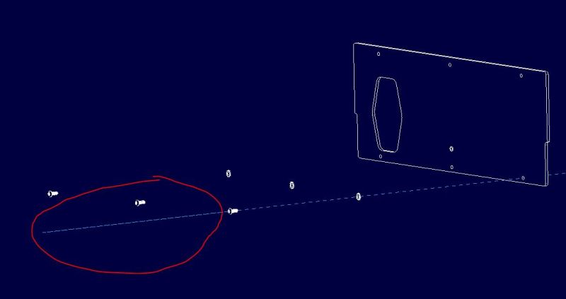
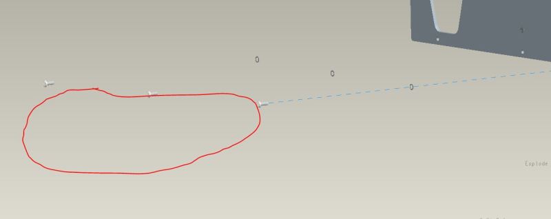
Edit: I have attached some pictures showing how the drawing and the model differ. Notice in the drawing how the explosion line shoots out of the top of the screw, but in the model, it does not.

RE: Explosion (offset) lines/ general explosion problems

You can't fix it. It's an internal problem. And Creo 2 does the same sort of thing.

In a discussion with PTC their rep indicated they might figure out the problem if I sent them all the models and the drawing, but I think they already know and just don't want to change the software.

RE: Explosion (offset) lines/ general explosion problems

(OP)
Thanks for the input. So why has it gotten worse over time? IF that is the case, then wouldn't an uninstall/reinstall remedy the problem for a little while? Also, the 2 other engineers, who have worked here for longer than I have, have never had these issues.

RE: Explosion (offset) lines/ general explosion problems

(OP)
I should also note that most recently, after adding explosion lines to 4 pages, when I clicked "save", the lines on every page other than the current page were deleted.

RE: Explosion (offset) lines/ general explosion problems

It's a corruption of the assembly file, not the software. As to the others, who knows.

RE: Explosion (offset) lines/ general explosion problems

(OP)
So what would cause the corruption? And how do I prevent/fix it? It is happening to all just about every assembly now.

RE: Explosion (offset) lines/ general explosion problems

You can fix the overshoot (for some reason that picture didn't load when I first saw this thread.) At least in Creo 2, I can edit the explosion line and look for the two handles; there is one for each end of the explosion line. Drag them towards the ends of the screw/hole.

I think the overshoot is because those handles represent intermediate points and there is a lower precision used on the drawing that causes their coordinates to not be in line with the end points. Since the line through the intermediate doesn't line up with the screw/hole, the software calculates an intersection, which is much farther away. There may be some other reason, but it's still PTC's failure to use exactly the same routines to display the model as to display the view on the drawing; not unlikely as it seems each group must not talk to each other.

RE: Explosion (offset) lines/ general explosion problems

(OP)
Thank you for the input! With all of that being said, is there anything you can recommend to prevent/resolve the issue? It does not happen all of the time, but has become more and more common as time passes. For this reason, I am inclined to believe that it has to do, in one way or another, with resources within the program or the PC being consumed or limited. To see such a progression in the occurrence and severity of the issue makes me think that if it can progress, it can regress. Or maybe the progressive symptoms are purely coincidental....

RE: Explosion (offset) lines/ general explosion problems

One major item to watch for when placing your lines in the exploded view is which HALF of the axis you select when placing the start and end of your lines. Creo (and all previous versions of Wildfire, and 2001) will select the END of the axis closest to where on the axis you click. In your pictures above, it appears that you may have selected the back half of the axis (the half closest to the screw head, rather than the screw tip). Creo then dropped the lines such that the end extends from the screw head AWAY from the part. The only way (that I know of currently, as of Creo 2.0 m130) is to delete the unwanted line and create a new one extending from the proper ends of the axes.

Red Flag This Post

Please let us know here why this post is inappropriate. Reasons such as off-topic, duplicates, flames, illegal, vulgar, or students posting their homework.

Red Flag Submitted

Thank you for helping keep Eng-Tips Forums free from inappropriate posts.
The Eng-Tips staff will check this out and take appropriate action.

Reply To This Thread

Posting in the Eng-Tips forums is a member-only feature.

Click Here to join Eng-Tips and talk with other members! Already a Member? Login


Resources

Low-Volume Rapid Injection Molding With 3D Printed Molds
Learn methods and guidelines for using stereolithography (SLA) 3D printed molds in the injection molding process to lower costs and lead time. Discover how this hybrid manufacturing process enables on-demand mold fabrication to quickly produce small batches of thermoplastic parts. Download Now
Design for Additive Manufacturing (DfAM)
Examine how the principles of DfAM upend many of the long-standing rules around manufacturability - allowing engineers and designers to place a part’s function at the center of their design considerations. Download Now
Taking Control of Engineering Documents
This ebook covers tips for creating and managing workflows, security best practices and protection of intellectual property, Cloud vs. on-premise software solutions, CAD file management, compliance, and more. Download Now

Close Box

Join Eng-Tips® Today!

Join your peers on the Internet's largest technical engineering professional community.
It's easy to join and it's free.

Here's Why Members Love Eng-Tips Forums:

Register now while it's still free!

Already a member? Close this window and log in.

Join Us             Close