Continue to Site

Eng-Tips is the largest engineering community on the Internet

Intelligent Work Forums for Engineering Professionals

  • Congratulations waross on being selected by the Eng-Tips community for having the most helpful posts in the forums last week. Way to Go!

Y14.5-2009 Fig. 4-16, option (c) 2

Status
Not open for further replies.

Burunduk

Mechanical
May 2, 2019
2,533
I would appreciate your assessment of my rationalization of why the 7.5 MMB boundary for datum feature D in fig. 4-16 option (c) is correct. Do not hesitate to nitpick on any inaccuracies that you detect. If you think something in the reasoning is incorrect, or incomplete - tell why. And if you would explain the final conclusion in a different way, please share it. My reasoning is as follows:

1. The calculation of the maximum material boundary of a datum feature referenced in a given feature control frame takes into account the virtual condition of that datum feature as imposed by its size tolerance and any geometric tolerance that controls the datum feature in reference to the datums that precede it in the said feature control frame, with identical order of precedence. As in all cases, datum shift is not part of the above mentioned virtual condition calculation.

2. The position tolerance in fig 4-16 applied on datum feature D imposes a 7.5 mm diameter boundary basically oriented to datum A, basically located from datum axis B, and aligned with datum centerplane C. This is the full information related to the said position control.

3. Derivative from (2), there is partial (but true!) information that can be provided about the maximum material boundary of datum feature B D related to the position control applied to it: it is a 7.5 mm boundary, basically oriented to datum A and basically located from datum axis B.

4. Directly based on (1) and (3) above, the MMB boundary of datum feature B in option (c) is 7.5. Also as noted in para 4.11.6.1, "Since the perpendicularity tolerance is a refinement of the position tolerance, it is not additive".
 
Replies continue below

Recommended for you

I discussed this and created a proof that this is a wrong conclusion as the diametral position tolerance is only observable in the defining DRF. Outside of that DRF it no longer applies. Since it is not in the defining DRF, but the perpendicularity is, the perpendicularity serves to limit the Virtual condition/MMB in a way that simple addition cannot describe.

See my posts:18 Dec 18 08:26 and 30 Jan 19 15:06 in For some reason the embedded images act broken; the links at the start of the post work.
 
3DDave,
Do I understand correctly?

The collection of locations where the surface of datum feature D is allowed to be with reference to A as primary and B(M) as secondary (which are part of the DRF of option (c)) is a 7.3 X 7.5 obround.

The 7.3 dimension results from MMC size plus the perpendicularity control applied to D with reference to A limiting the surface orientation cylindrically.

The 7.5 dimension results from MMC size plus position control applied to D limiting its location up to "+/- 0.2", only in the specific direction that connects datum axis B and the axis of the RAME of D, because rotation around B is unconstrained in the "sub-DRF" where MMB of D is evaluated. This one-directional boundary added to the perpendicularity boundary leads to an elongated total boundary in the |A|B(M)| sub-DRF.

Is this the way you see it?
 
Did you examine the figures or are you looking at the previous and, for me, discarded discussion? I ask because the shape is not merely obround. Those are the dimension limits, but it's wrong to characterize the shape as obround.

Are you looking for me to repeat what I previously wrote and made explicit with the software?
 
I looked again in the figures and it is indeed not obround, I suppose I was distracted by the obround shape mentioned in the discussion in that thread or a related thread that preceded the figures, trying to figure out the limiting dimensions of the shape (which are not indicated in the figures you posted or mentioned in the post where the figures are unless I missed it). My apologies. So I understand according to your last post here, that the 7.3 X 7.5 limiting dimensions are still in force for the total width and total height of the shape, even if it is not obround.

Does the elongated shape and the 7.3 X 7.5 dimensions also represent your suggestion for the shape and size of the datum feature simulator of datum feature D for the position control in option (c) of the figure or is this an evaluation only for the purpose of discussion of how the surface of datum feature D is limited by the controls applied to it in the different datum reference frames? I believe that where the obround shape was discussed, you suggested that the datum feature simulator should be a slot. Is this still your approach, only with the accurate shape involved?

 
It would have been nice if the ASME committee had figured this out for themselves. But even Mr. Meadows, in charge of some large part of the gauging standard, thought I was entirely wrong.

Since B(M) allows radial movement that D(M) can restrict, then it should follow the odd profile as calculated by the software. If one wanted to force it to be a radial slot, there are established means to do that without adding hand-waving interpretations as the gauge making group wanted.
 
The intent of the standard in calculating the MMB boundary for each datum feature in fig. 4-16 and the related paragraphs seems to be setting a datum feature simulator size that will not violate datum precedence. D(M) is referenced tertiary in the option (c) DRF and should constrain only the rotation around datum axis B. Had it been referenced secondary, the size of the MMB datum feature simulator would be 7.3, with a cylindrical shape, as in option (b). The question that arises is - if datum feature D at MMB tertiary is simulated by the elongated internal simulator limited to 7.3 mm "height", can't it potentially violate datum precedence? The related actual mating envelope of datum feature D can be 7.3 mm, resulting from MMC size plus the perpendicularity tolerance WRT A. Therefore it seems that a scenario is possible where this simulator might constrain a translational degree of freedom that datum feature simulator B(M) should constrain, despite a sequential datum feature simulation. I may be wrong. Am I?
 
Maybe if they want to avoid datum precedence violation they need to avoid nonsense callouts which are papered over with useless simplifications.

By datum precedence violation, I assume you mean that the datum feature simulator at D(M) will contact some variations of datum feature D and prevent some variations of datum feature B from moving to every possible location within datum simulator B and therefore can control location that somehow only datum feature B should be allowed to. Which can happen with hole patterns anyway.
 
Burunduk said:
The question that arises is - if datum feature D at MMB tertiary is simulated by the elongated internal simulator limited to 7.3 mm "height", can't it potentially violate datum precedence? The related actual mating envelope of datum feature D can be 7.3 mm, resulting from MMC size plus the perpendicularity tolerance WRT A. Therefore it seems that a scenario is possible where this simulator might constrain a translational degree of freedom that datum feature simulator B(M) should constrain, despite a sequential datum feature simulation. I may be wrong. Am I?

This is actually possible in any |A|B(M)|D(M)| or |B(M)|D(M)| scenario regardless of the shape of the datum feature simulator D.

The way to avoid this is to define the size of the datum feature simulator D:
- smaller than MMB of D by at least the |LMCB-MMBB| value, when D is internal feature of size, or
- larger than MMB of D by at least the |LMCB-MMBB| value, when D is external feature of size.

This can be done by putting the required size of the simulator D in brackets after the datum letter D in the FCF, as shown in para. 4.11.6.3 in Y14.5-2009.
 
I think defining the size of the simulator makes things worse. The zone that the feature can occupy isn't a cylinder, so either the distance goes unaccounted for or the tangential width is overly large, or some other combination.

I suspect the only way out is to just draw the exact mating boundary with basic dimensions to represent the expected virtual boundary allocated to the mating part. This is one function of the current FCF system - to develop a do-not-cross boundary that should match the mating part's do-not-cross boundary.
 
3DDave,

My reply wasn't specifically referring to fig. 4-16 (c), although it looked like it was because I used the same datum letter convention. It was more like a general statement for all other cases where these two types of DRFs are used.

In case of fig. 4-16 (c), I agree that the exact shape of the expected simulator D would have to be drawn and defined with basic dimensions. But this still doesn't mean that there would be no problems with the DOF constraint order of precedence. To avoid this the size of the simulator D would still have to be made smaller than the MMB size (offset from the MMB) by at least the value calculated from the formula given in my previous reply.
 
And as I think of it more, I am not even sure that defining the size of the simulator D different than at its MMB size will really help a lot (at all?). I guess it because for DRFs like |A|B(M)|D(M)| or |B(M)|D(M)| it is rather impossible by just applying tolerances on the drawing to force the real part to behave in the simulator in a way that D at MMB always constrains just the last rotational DOF.

I am thinking that the correct solution should either be defining B at RMB (by that B will always constrain translational DOFs) or define B(M)-D(M) as common datum feature at MMB (and by that let the actual as-produced geometry decide which datum feature will constrain which DOF).
 
B at RMB forces the virtual condition of D relative to B to include the potential variation of B if D was originally defined relative to B at MMB.
 
I didn't say D should be defined relative to B at MMB. Generally, I am not a fan of defining the same datum feature at different boundary conditions on the same drawing.

And again, my last reply was general, not specifically about fig. 4-16.
 
pmarc said:
And as I think of it more, I am not even sure that defining the size of the simulator D different than at its MMB size will really help a lot (at all?). I guess it because for DRFs like |A|B(M)|D(M)| or |B(M)|D(M)| it is rather impossible by just applying tolerances on the drawing to force the real part to behave in the simulator in a way that D at MMB always constrains just the last rotational DOF.

I don't understand why. The scheme you described in your 7 Feb 20 21:14 post makes perfect sense to me. Considering fig. 4-16, if we think just of the datum precedence order and put aside the issue of the exact shape of the actual worst-case boundary for D, then if I set a simulator value for datum feature D to be 7.7; which results from 7.5 (the larger dimension of the elongated MMB shape) plus the difference between LMC and MMB of B - which is 0.2, I can apply this datum reference frame:
|Position|dia.0.3|A|B(M)|D(M)[dia.7.7]| for controlling the dia 3.5 mm hole.
I think this should ensure that datum precedence order is not violated and each datum feature simulator constrains the degrees of freedom as intended. That is because the clearance between actual datum feature D and the datum feature simulator D will always be larger than the corresponding clearance for B, therefore B will constrain translational degrees of freedom before D is able to. What am I missing?

Edit: To take care of the worst-case scenario of both datum features constraining translation, the 7.7 value in the above calculation can be replaced by 7.75.
 
What are you missing? That is an excellent question. I would have thought the reason for referring to D was to get the hole somewhere close to the middle of the feature, at least tangentially relative to B, but by adding even more variation it's quite possible the hole won't need to hit within D at all. Do you agree that this is the best outcome? What does the minimum mating part look like and will this part always fit it?
 
I think that the datum reference frame in option (c) suggests that coaxiality to D is only a marginal concern of the design. It seems like the intent is more accurate location from B. The most accurate coaxiality (out of the given options) is ensured by option (a). The dimensions and tolerances should ensure that the hole hits within datum feature D with sufficient wall thickness despite the additional variation caused by more datum shift.
 
Burunduk said:
I think this should ensure that datum precedence order is not violated and each datum feature simulator constrains the degrees of freedom as intended. That is because the clearance between actual datum feature D and the datum feature simulator D will always be larger than the corresponding clearance for B, therefore B will constrain translational degrees of freedom before D is able to. What am I missing?

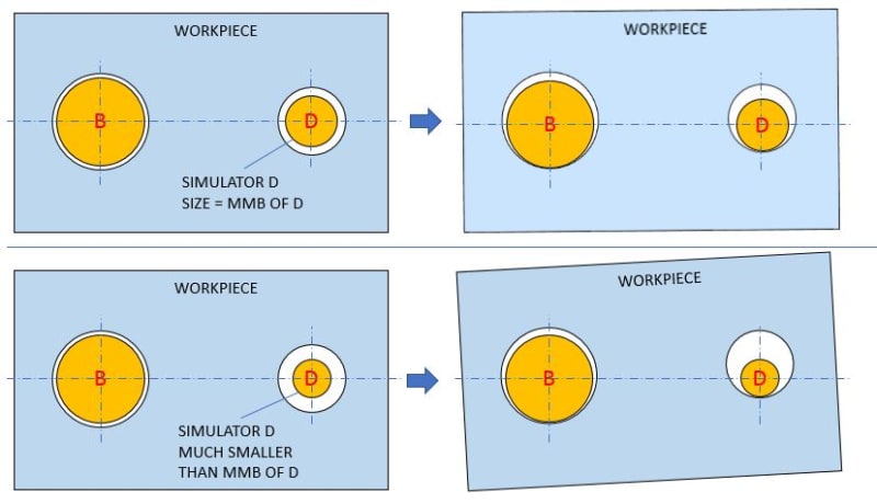
The problem is (I am talking generally, not specifically about fig. 4-16) that regardless whether the simulator D size is smaller (for datum hole) or greater (for datum pin) than the MMB size of D, the mechanism defining a workpiece-to-simulator relationship is still the same. And based on just looking at the final effect it is impossible to tell in both cases which of the two simulators constrained which degree(s) of fredom and in what order.

snap_agmcfk.jpg
 
pmarc, that's a very good graphic. I can see that in terms of the final result, it is indeed impossible to tell which simulator constrained what type of movement. From the conditions shown at the right side and on, both act like a "multiple datum feature" (as in para. 4.12).

However, I think that sequence is important. In both top and bottom cases, After the shown workpiece started moving "up", the simulator that touched its corresponding hole constrained the translation. From there and on, the movement became rotation. So, it seems to be dependent on the initial orientation of the part in the fixture. The simulator that was closer to the corresponding hole surface initially acted as the translation constraining simulator. For the initial orientation as shown on the left side in both cases (holes being coaxial with the simulators), I think that it is the B simulator that constrained the "up" movement of the part, based on the smaller simulator-hole clearance at B. I realize that the movement could be some kind of combined translation-rotation from the start, and under specific conditions, even with the shown initial orientation they could touch simultaneously, or D first, but that doesn't seem to me like "translation" being locked per the intent of the standard.

What is interesting to note is that the problem seems to be very unlikely (impossible?) for the "left-right" translation. It seems like the only simulator that can make contact prior to the part being forced to rotate is B.
 
Status
Not open for further replies.

Part and Inventory Search

Sponsor