Burunduk
Mechanical
- May 2, 2019
- 2,580
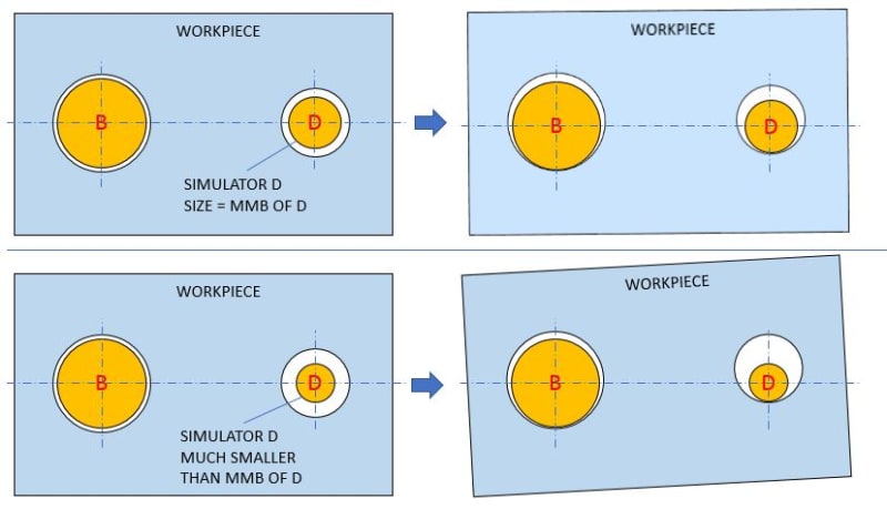
I would appreciate your assessment of my rationalization of why the 7.5 MMB boundary for datum feature D in fig. 4-16 option (c) is correct. Do not hesitate to nitpick on any inaccuracies that you detect. If you think something in the reasoning is incorrect, or incomplete - tell why. And if you would explain the final conclusion in a different way, please share it. My reasoning is as follows:
1. The calculation of the maximum material boundary of a datum feature referenced in a given feature control frame takes into account the virtual condition of that datum feature as imposed by its size tolerance and any geometric tolerance that controls the datum feature in reference to the datums that precede it in the said feature control frame, with identical order of precedence. As in all cases, datum shift is not part of the above mentioned virtual condition calculation.
2. The position tolerance in fig 4-16 applied on datum feature D imposes a 7.5 mm diameter boundary basically oriented to datum A, basically located from datum axis B, and aligned with datum centerplane C. This is the full information related to the said position control.
3. Derivative from (2), there is partial (but true!) information that can be provided about the maximum material boundary of datum featureB D related to the position control applied to it: it is a 7.5 mm boundary, basically oriented to datum A and basically located from datum axis B.
4. Directly based on (1) and (3) above, the MMB boundary of datum feature B in option (c) is 7.5. Also as noted in para 4.11.6.1, "Since the perpendicularity tolerance is a refinement of the position tolerance, it is not additive".
1. The calculation of the maximum material boundary of a datum feature referenced in a given feature control frame takes into account the virtual condition of that datum feature as imposed by its size tolerance and any geometric tolerance that controls the datum feature in reference to the datums that precede it in the said feature control frame, with identical order of precedence. As in all cases, datum shift is not part of the above mentioned virtual condition calculation.
2. The position tolerance in fig 4-16 applied on datum feature D imposes a 7.5 mm diameter boundary basically oriented to datum A, basically located from datum axis B, and aligned with datum centerplane C. This is the full information related to the said position control.
3. Derivative from (2), there is partial (but true!) information that can be provided about the maximum material boundary of datum feature
4. Directly based on (1) and (3) above, the MMB boundary of datum feature B in option (c) is 7.5. Also as noted in para 4.11.6.1, "Since the perpendicularity tolerance is a refinement of the position tolerance, it is not additive".

