Continue to Site

Eng-Tips is the largest engineering community on the Internet

Intelligent Work Forums for Engineering Professionals

  • Congratulations waross on being selected by the Eng-Tips community for having the most helpful posts in the forums last week. Way to Go!

Wood stairs moment connection

Status
Not open for further replies.

Buleeek

Structural
Sep 5, 2017
98
Hello everyone,
This is my first post on this forum, however, I've been reading threads for quite some time. Thank you for all your help!
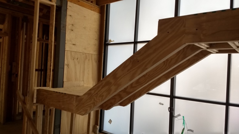
I have a question about a moment connection in a wood frame. Attached to this post is a sketch with an issue I'm dealing with. Could you please look at the sketch and tell me what do you think I should use to carry a moment at the stringer/joist connection? In addition to that, is there any way to reduce the deflection other than more material (sistering a stringer)? I have never designed a moment connection in wood so any help would be appreciated.
2x12 SPF#2

Thank you,
 
 http://files.engineering.com/getfile.aspx?folder=36980ed7-51ec-484a-ae99-6b23a747840c&file=Stair_moment_connection.pdf
Replies continue below

Recommended for you

Can you post a floor plan of the stair area? Is there any reason why you can't frame the stair landing with typical floor joists? Typically your landing would have a double or triple floor joist at the stringer location to pick up the load from the stringer.
 
Moment connections are possible in wood but it's usually mass timber stuff with fancy hardware or dirt simple joist sistering exercises. In my opinion, a moment connection like this, involving a direction change and a reduced throat, is impractical. Especially so if you'r goal is the control of deflection/vibration. Whatever moment connection you come up with is likely to have a fair bit of give in it at the early stages of loading. If it's a repair, perhaps you could glue on some gusset plates and hope for a qualitative performance enhancement. If it's new construction, I'd try to find another way as shotzie has intimated.

I like to debate structural engineering theory -- a lot. If I challenge you on something, know that I'm doing so because I respect your opinion enough to either change it or adopt it.
 
It is not a repair. New stairs are being installed, and this is an architect concept. My idea was to install a beam at the top of the stairs and "hang" it to the ceiling with a 4x4 railing post.
Floor plan of the stair area is attached. There is nothing on the "left" site of stairs. There is a wall on the right side.

Thanks
 
 http://files.engineering.com/getfile.aspx?folder=24fd2c36-fbdb-484b-bfef-225c5740e36c&file=stair_moment_connection.png
Agree with the posters above. Do not do this. Find another way. As Kootk indicated there will be some significant slip in the construction at the early stage, and then long term creep after that. Before long your landing will have a pretty significant slope to it.
 
Can you cantilever a new triple floor joist over the existing wall (on the right side of the stair) to pick up the stringer? Or install a new double/triple beam in the existing wall going up down at the bottom left corner of the landing that cantilevers out to allow for conventional floor joist framing for the landing? As the others have mentioned the proposed cranked wood frame likely won't work.
 
As an aside, you might be able to do some sort of cantilevered stair off of the existing wall Link. I personally haven't used this on a project yet, but it might be an option to consider.
 
I'm afraid I can't cantilever the steps. The architect said he will send me calculations of their engineers who supposedly have done something like this several times. We will see, I will let you know. Thanks for all the advice!
 
Ohh... post those calcs. KootK smells blood in the water...

There's one version of this I might be able to get behind:

- bottom of the stringer fixed against lateral translation.
- top of the landing joists fixed against lateral translation at end opposite the faux moment connection.
- just enough of a bullshit moment connection that you can call the thing rigid body stable-ish.

Toss that out to your architect before the calcs show up to ensure that these other guys don't look sharper than you. "Here's one, somewhat questionable, approach...".


I like to debate structural engineering theory -- a lot. If I challenge you on something, know that I'm doing so because I respect your opinion enough to either change it or adopt it.
 
There is another possibility but it is a little unconventional. Design stair and landing as a three hinged arch but make sure that the horizontal reaction can be taken at each end.

BA
 
Here are some things that I have done in similar circumstances that might be possible for you:

Make the stringers out of plywood layers (with multiple 8 ft sections in the middle 8 feet).
This might not work well due to the relatively shallow section available at the tread/riser zones.

Use steel flitches for the stringers.
You might be able to use a channel or tube section placed at the edge (as a way to avoid making 4 or 5 flitches) and then frame the landing off of the flitch.

I like BA's suggestion too. The whole thing doesn't seem so big that it can't be managed with wood and well positioned anchorage.

Steve

 
Buleeek:
With too many Archs. these days, nothing is impossible or too expensive when it comes to the edifice they are building to show their design talents; that is, as long as it is someone else’s responsibility to make it work without any problems and as long as they can blame that other party for the ridiculous extra costs and efforts involved in their perfect design. To often, they have no idea why it won’t work or isn’t a good idea, and they don’t seem to give a damn. They (or CAD) can draw it, so it must work. I would design cranked steel stringers spanning from the lower floor, up the steps plane to landing plane change and on to the LVL. Make the bot. flg. about 4" wide and centered on the web. Make the web shallow enough so as to miss/clear the tread/riser cuts on the 2x12's at the steps. Make the top flg. one sided, and thicker, like a channel flg. Have the fab’er. weld some threaded studs on the opp. side of the web (away from the top flg.) to fix the sistered 2x12 stringer framing to the steel. The wood stringers bear on the bot. stl. flg., with the bolts sistering them Install some wood blocking for stability. This is all done for Arch. sex appeal, at great expense. A few 4x4 posts with invisible paint would work better. :)
 
IMG_20170803_101354952_HDR_rxmsa1.jpg

We asked for calcs for this stair 'z' wood stringer and never received any.
 
In my opinion, if you're thinking about having custom steel plates fabricated to create a connection that won't work well, you might as well go ahead and make the stringers with C shapes. Add clips to attach treads, if necessary, and/or holes so that wood can be easily attached to the steel. The whole thing can be wrapped and trimmed in wood. They can probably have one made for a few hundred $US, or whatever your commonly accepted local currency.
 
I have not done it for a stair, but maybe a flitch plate arrangement would work.
 
That looks like a pretty big steel column in the wall at the end of the stairs (in the pic from nac521).
Maybe there's a "yardarm" on there holding things up.
I've done similar things before.

 
Status
Not open for further replies.

Part and Inventory Search

Sponsor