Continue to Site

Eng-Tips is the largest engineering community on the Internet

Intelligent Work Forums for Engineering Professionals

  • Congratulations waross on being selected by the Eng-Tips community for having the most helpful posts in the forums last week. Way to Go!

Wood Shear Wall Software or Spreadsheets 2

Status
Not open for further replies.

medeek

Structural
Mar 16, 2013
1,104
For residential design I typically run with segmented shearwalls that I manually calculate and check using the SDPWS-2008. However, I am wondering what if any specialized software or spreadsheets that others might use for looking at shearwalls (segmented, perforated, force transfer) or possibly recommend. What is common practice in this area?
 
Replies continue below

Recommended for you

If you look at Simpsons detailing requirements, it pretty much resolves all the worries you guys are looking at with rebar. If you put transverse bars in your footing, and show the anchor below those, you have just engaged much more than a typical shear cone. I will post a detail tomorrow for mid-wall and corner conditions using the Simpson walls.

I really like the KISS principal :) and believe me, I've been told to "KISS" it a lot.
 
@KootK - Not to side track here but... I've often wondered about reinforcement for burst forces when dealing with anchorage design. Are there any references on designing for this or maybe you can shed light on how you approach that situation? Similar to how ACI prestressed concrete strut and tie addresses these forces?

EIT
 
RFeund - I don't know ACI well, but any modern code with Strut and Tie provisions should handle this without issue.

There are a few basic "magic" points to Strut and Tie:

- Determine your B and D regions (this is a fancy way of saying "Design beam like sections as beams, and stout/squat sections as Disturbed regions"). In Strut and Tie, B regions are designed like regular beams, with compressive struts and ties parallel and running the length. Your D regions are where the shear span is less than 2 to 2.5 the beam depth.
- 22.5deg minimum strut angle.
- Check your tiess.
- Check your struts.
- Check your nodes (aka anchorage zones, assumed points of stress flow change).

There are some great resources online for learning this. One of my favourites is a paper from IIT in India.
 
@RFreund: I've actually had a hard time sorting out bursting requirements myself. I've borrowed ideas from PTI and from Widianto's now classic paper on pedestal design. I think Widianto's recommendation amounts to a lateral force to be restrained equal to about 1/4 of the anchored force. What I'd really like is to know at what level nothing needs to be done to restrain bursting stresses. There's gotta be something better than just plain old bearing provisions.

I like to debate structural engineering theory -- a lot. If I challenge you on something, know that I'm doing so because I respect your opinion enough to either change it or adopt it.
 
Burst forces are essentially what you're doing at a compressive node. The model is layed out and the reinforcement is detailed to such that the forces involved do not exceed the capacity of the node. The "bursting forces" you're talking about are more applicable when you cannot control the strength of the system, such as with a post-tensioned system.

What am I missing that you two are debating this?
 
Base upon your elevation picture above, I would try a horizontal beam (exterior to exterior) at the top of the lower windows. Designing the above as a wood frame (at the wall studs with wood panels) with posts down to the beam to transfer the lateral force and moments. This way you can transfer the above lateral forces as a shear to the beam with the moment being taken out as an uplift/downward forces on the beam.

Garth Dreger PE - AZ Phoenix area
As EOR's we should take the responsibility to design our structures to support the components we allow in our design per that industry standards.
 
RE Bursting Forces:

I think I may be getting things confused... The bursting forces involved in anchorage design are really geared toward side face blow (or so I think).

Widianto said:
When the reinforcement is used to restraint concrete side-face blowout, it should be
designed to carry the lateral force causing the side-face blowout. Cannon et al. (1981)
indicated that for conventional anchor heads, the lateral force causing side-face blowout
may be conservatively taken as ¼ of the tensile capacity of the anchor steel (based on the
Poisson effect in the lateral direction). A more complex procedure to calculate the lateral
force is given in Furche and Elingehausen (1991). In general, the Furche and
Elingehausen’s procedure gives a smaller lateral load than that recommended by Cannon
et al. (1981).
Also note that
Widianto said:
It should be emphasized that
transverse reinforcement (ties) did not increase the side-face blowout capacity (DeVries
et al. (1998)). Large amount of transverse reinforcement installed near the anchor head
only increased the magnitude of load that was maintained after the side-face blowout
failure occurred

So where my confusion was...
When looking at KootK's sketch on 26 Dec 14 18:47 and seeing the bursting restraint bars, I was wondering how to calculate how much steel is required there. The answer to that seems to be answered by Widianto and KootK (about 1/4 the tension). However to answer the question of "when is it required and how effective is it" is a bit unknown to me. It seems as though it would be required when side face blow out is an issue. It does not effect concrete break-out strength (which I believe I have confused this part in the past). Widianto states that transverse reinforcement does not prevent side face blow out but does "increase the magnitude of the load that was maintained after s-f-b. He also states that "When it is impossible to provide the minimum edge distance of 6do, the side-face blowout strength should be calculated using Section D.5.4 of the ACI 318-05". So it seems as though you don't really gain any strength from a code standpoint by providing "bursting reinforcement" (aka side face blowout reinforcement.

EIT
 
Woodman88 the problem I have with putting the beam across the wall at the top of the lower windows is that I then create a hinge point for the columns holding up the central glulam beam. I have about 5000lbs total load on each column I also have strong out of plane wind forces hitting the wall. The bending and hence deflection of this beam along its weak axis would be fairly significant and with no lateral bracing the combination of the columns compression acting near the center where there is max. deflection would be problematic.

A confused student is a good student.
 
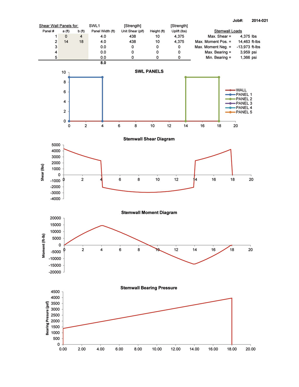
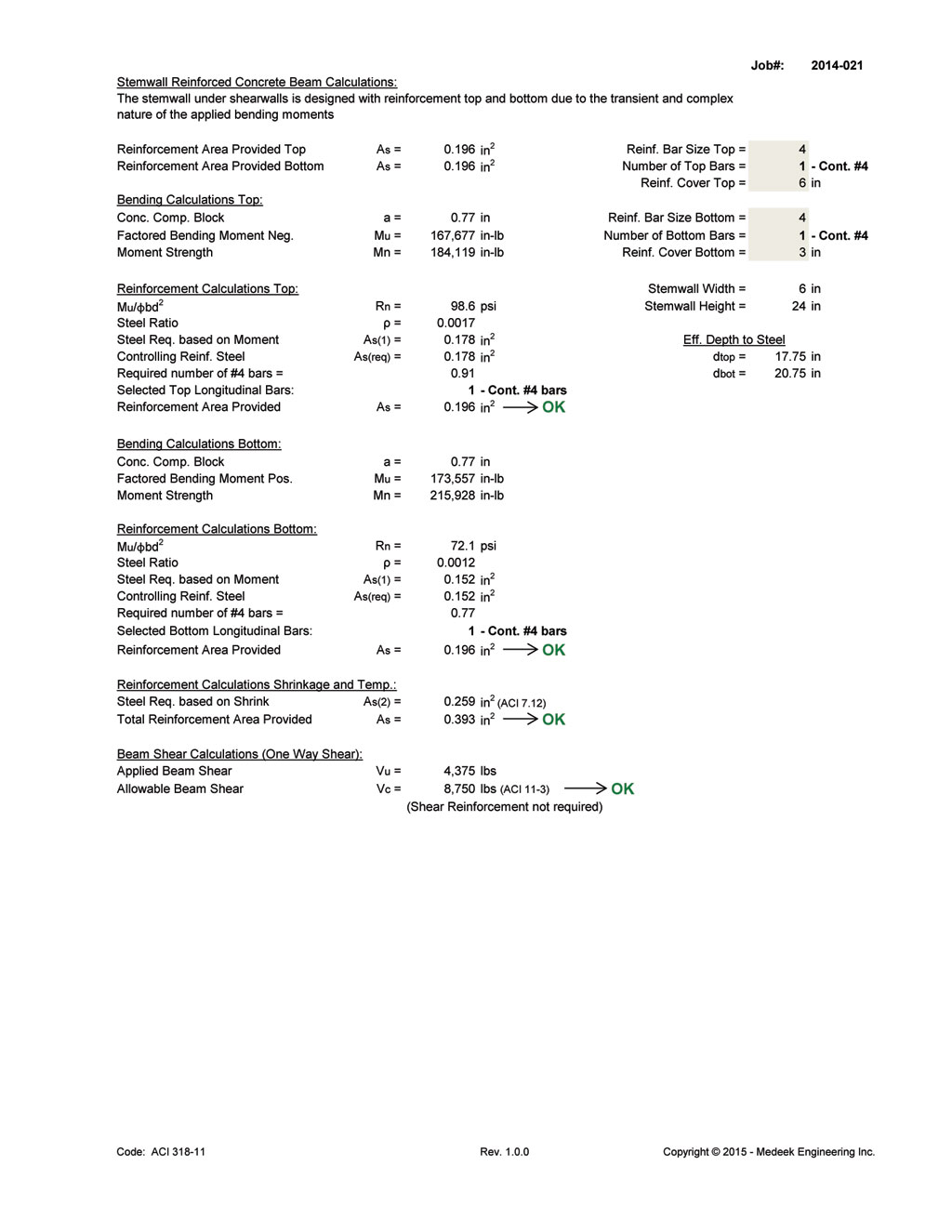
I kind of have two threads going on here that probably should be merged. Here is the updated stemwall calc. output. The spreadsheet can be downloaded here if anyone is interested:


I'm still really new to concrete so if you see something completely amiss please let me know. I based my calcs off of the following references:

ACI318-11
ASCE7-10
Simplified Design of Building Foundations by James Ambrose
Design of Reinforced Concrete 7th Edition by James K. Nelson
The Analysis of Irregular Shaped Structures by R. Terry Malone

2014-021_STEMWALL_SHEARWALL_FOOTING_REV3_2.jpg


2014-021_STEMWALL_SHEARWALL_FOOTING_REV3_3.jpg


2014-021_STEMWALL_SHEARWALL_FOOTING_REV3_4.jpg


A confused student is a good student.
 
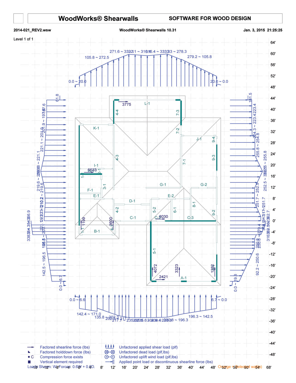
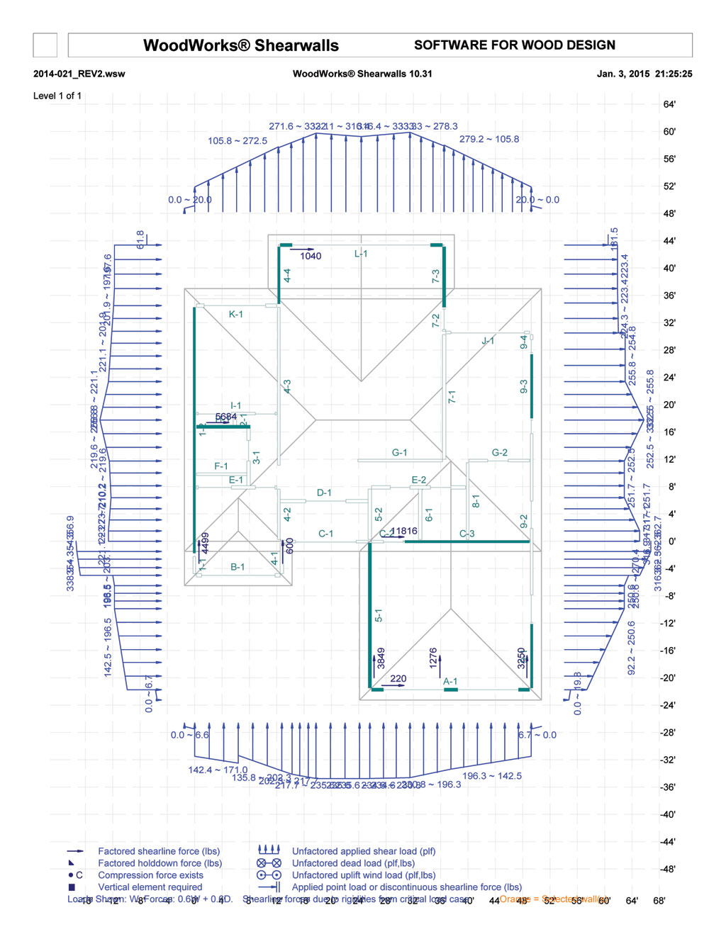
Woodworks output for the above residence for Flexible and Rigid Wind Loads:

2014-021_WW_WIND_FLEXIBLE.jpg


2014-021_WW_WIND_RIGID.jpg


I used the more conservative directional procedure rather than the envelope procedure. As I have found with my own manual calcs the seismic for a one story building does not govern in my locality, wind speeds are 155mph (ultimate).

As you will note, I was unable to correctly model the diagonal walls since Woodworks does not provide this capability. Perhaps someone has a suggestion in this regard or a better method for simplifying the analysis.

I've manually calculated wind loads on cut up roofs on other projects similar to this however my diaphragm loads were probably never quite this granular. There is something to be said for just putting in the geometry and having the program spit out the entire load take down. It still worries me a little as to how the program distributes the loads to the shear walls, I guess I'm not a fan of black box results but I do see the utility of it.

What had me stumped for almost an hour though was why it was giving me such high seismic shear loads. Then I went back through the settings and realized it had my Response Modification Factor set at "2" because of the gypsum on the other side of the ext. shear walls. Once I set this to 6.5 everything was it should have been and my seismic loads made sense.

A confused student is a good student.
 
The allowable for my SWSB18 (Simpson StrongWall SB) is 1475 lbs for wind at a 12ft. height I'm over that at about 1880 lbs per the flexible diaphragm wind load however in reality I think the loading will be a semi-rigid diaphragm situation since the tall Simpson walls will deflect and the much stiffer exterior walls will pick up the torsional loadings. This is clearly shown in the rigid diaphragm loading with the much higher loads on the most exterior walls running North and South.

To envelope the design as much as possible I will spec. out the sheathing and holdowns with the worst load case from either the rigid or flexible analysis. This may be overly conservative but I want to try and pick up as much load from the wall of windows as is reasonably possible.

The one other annoying thing about Woodworks that I noticed that I thought might be worth mentioning is that along any given wall line it only allows one type of shearwall to be specified or one type of non-shear wall. It does not seem possible to have two different non-shear wall panels with different sheathing specifications. I don't know if it changes the output significantly or not but on some wall lines I have walls that are exterior and some that are interior (both non-shear). You wondering in anyone else has noticed this and how they have dealt with it.

A confused student is a good student.
 
For the wall of windows I get the following with the calculator:


Which gives me an 8" x 24" stemwall, with a 22" x 12" footing. The stemwall width and footing depth and width are governed by the requirements of the Simpson SWSB. The footing requires two longitudinal #5 bars for shrinkage and temp, no transverse reinf. required. The stemwall, due to the high uplift of the shearwall requires (2) #5 bars at the top and (2) #4 bars at the bottom, with vertical bars in the high shear areas for shear reinforcment (#4 bars vert. @ 12" o/c).

A confused student is a good student.
 
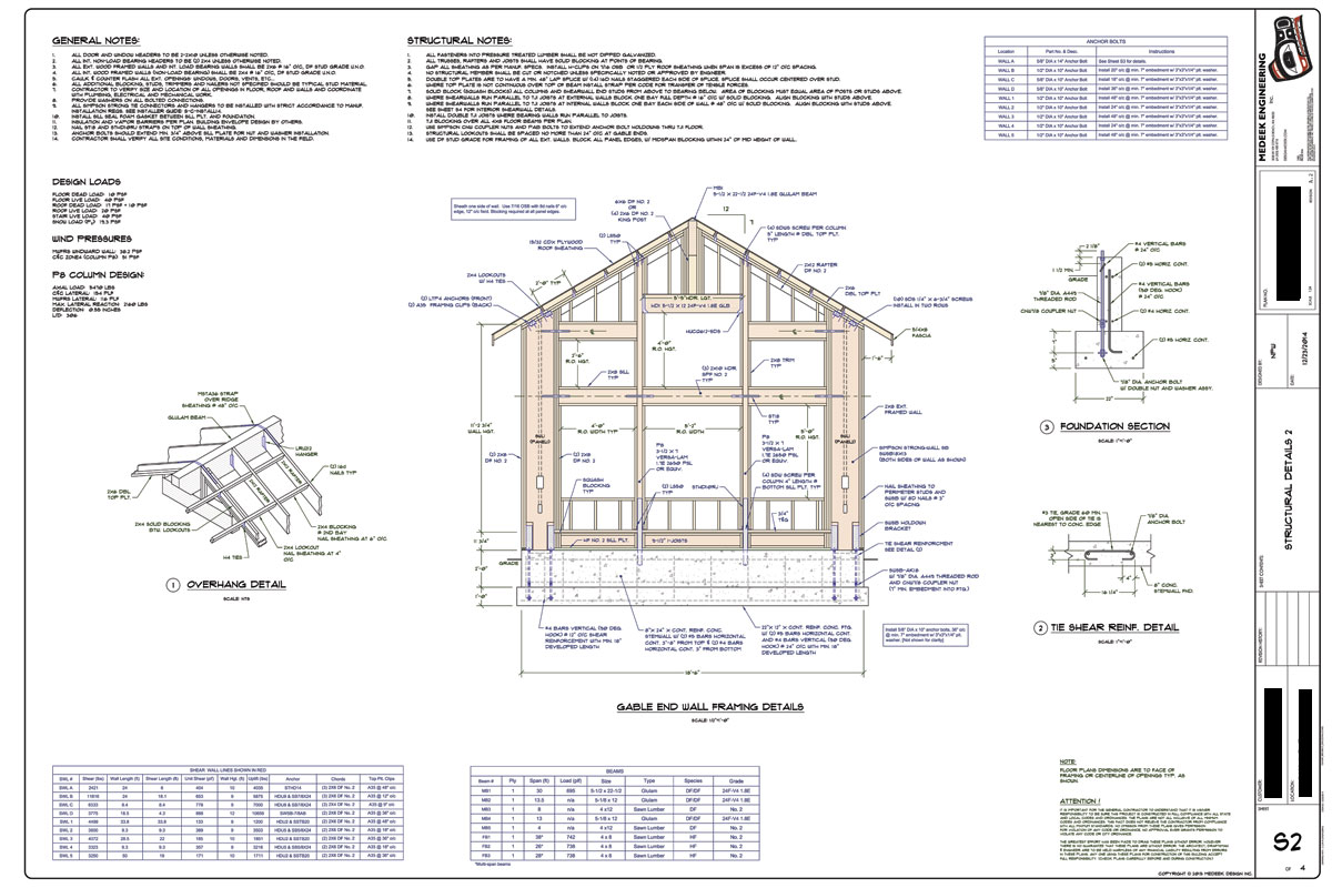
Here is the final detail drawing for that wall. I can already see some correction are in order, it is funny how you don't see the errors when it's in AutoCAD but as soon as you print it out they pop out all over the place.

WALL_OF_WINDOWS2.jpg


A confused student is a good student.
 
I've been giving my shearwall/stemwall calculator some additional thought and I just realized that unlike the bearing pressure of the footing on the soil, the bearing pressure of the stemwall on the footing can also have tensile values because of the vertical bars (typically 24" o/c) between the footing and the stemwall. Currently my calculator treats the interface like there is no vertical bars so only compression is transferred. I guess my question is how does this tensile capacity change the shear and moment diagrams of the stemwall which are driving my concrete reinforcement design. Of course this only becomes an issue when the resultant force is outside the kern of the shearwall.

I have also not determined the best way to deal with contributions from adjacent walls to help counteract the overturning of a footing under a shearwall. The latest residence was able to work out mostly but when I ran the numbers on the interior shearwall at the closet (8.4 feet in length) it did not work out for either overturning or sliding. The only way to make it work in this respect was to assume that the foundation walls and footings it connected to provided enough additional resistance to counteract the high lateral loads. The shearwalls tributary dead loads were not enough. However, how much does one assign from the other connected walls to provide this additional overturning resistance?

A confused student is a good student.
 
If the load falls outside of the kern and the vertical rebar is sufficient to take the footing along for the ride, the footing and a wedge of soil above it become downward load on your stem wall.

You can take as much tie down resistance from perpendicular walls as you need so long as equilibrium is satisfied and there's a capable load path available for the tie down force to develop. Foundations can be a bit nebulous in that there's a lot of continuity and it's tough to know exactly what load goes where.[pre][/pre]

I like to debate structural engineering theory -- a lot. If I challenge you on something, know that I'm doing so because I respect your opinion enough to either change it or adopt it.
 
Just adding concrete is the typical way to make the footing work for uplift. Your CYA vs construction cost savings is better this way.

Garth Dreger PE - AZ Phoenix area
As EOR's we should take the responsibility to design our structures to support the components we allow in our design per that industry standards.
 
I really thought this thread was done but a short postlogue is due given some interesting feedback from the contractor building this residence. Apparently he is not a fan of any type of Simpson Shearwall product and has been giving me a bad rap for using it on this particular design. With the aspect ratios what they were and the lack of any shearwall space on the structure I feel that I was forced into this decision otherwise the design would have had to been altered in some way which was not an option.

The worst part is this exact design has been built by him at least 4 other times (prior to any engineering being required by the jurisdiction and an inspector that actually checked the plans) so my calling out shearwalls and special hardware all over the place appears like serious overkill to him.

I think part of the problem here is that most of the contractors are used to building whatever and however they want and I am fighting that right now. So now I've gained the reputation,"His prices are reasonable but construction costs of his engineered designs are high."

A confused student is a good student.
Nathaniel P. Wilkerson, PE
 
I feel your pain. Responsibility for public safety + imperitive to compete in free market = perpetual low grade ethical compromise. It's a gods damned race to the bottom I tell you!

I like to debate structural engineering theory -- a lot. If I challenge you on something, know that I'm doing so because I respect your opinion enough to either change it or adopt it.
 
I'm with you on this one as well. In fact, I believe I made a comment about this exact thing earlier in the thread.

Most carpenters (and more specifically residential framers) think anything more than commodity lumber, plywood and a nail-gun is overkill. Once you start making them block shear walls and provide proper connectors and tie downs etc. they call it overkill.

You need to find a happy medium, wood is fairly proficient at load sharing (even if you can't adequately analyze it). One thing I have noted, when you need a hefty simpson product, sometimes it's cheaper to just custom fab a steel plate connector to fit the purpose. A lot of the contractors have a buddy with a steel shop (at least in my experience).

I also in these type of scenarios (tall walls of windows) talk to the contractor the first day about that specific wall. Including describing to him an overkill preliminary framing for the wall and then talk to him about the option of looking into steel framing. That way when the design in finalized he had his say on day 1 and can't grumble about the outcome at the end.
 
"His prices are reasonable but construction costs of his engineered designs are high."

Ultimately, you will have to turn this around and make your prices higher, but the cost of construction easy and cheap.
The more experienced you get, the more it will go this way.
 
Status
Not open for further replies.

Part and Inventory Search

Sponsor