Continue to Site

Eng-Tips is the largest engineering community on the Internet

Intelligent Work Forums for Engineering Professionals

  • Congratulations waross on being selected by the Eng-Tips community for having the most helpful posts in the forums last week. Way to Go!

Wood Shear Wall Software or Spreadsheets 2

Status
Not open for further replies.

medeek

Structural
Mar 16, 2013
1,104
For residential design I typically run with segmented shearwalls that I manually calculate and check using the SDPWS-2008. However, I am wondering what if any specialized software or spreadsheets that others might use for looking at shearwalls (segmented, perforated, force transfer) or possibly recommend. What is common practice in this area?
 
Replies continue below

Recommended for you

I'm glad that you are getting something of value as well from these discussions, KootK. However, I would take some of my older details on the website with a grain of salt, I really need to go back through all of them and update and/or correct a few of the more offending ones.

The ability to cut the Strong-Wall SB is a huge plus, can't do that with a steel strong wall. Okay, I think we have a game plan here, now to execute.


A confused student is a good student.
 
Make sure to pay attention to the foundation requirements for the walls...basically the same as you would do for the steel strong walls.

On another note, not related to shear walls but beams, Boise Cascade produces a "King Beam". It's a great product and cheaper than other engineered beams if you need something other than a typical glulam. Just thought I would throw that out there since you are relatively "new" to wood design. Lots of designers don't know about it.
 
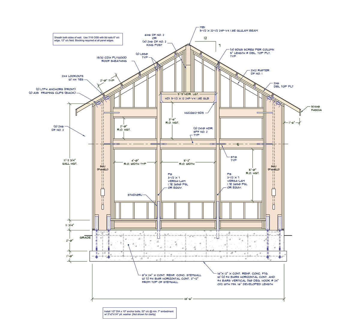
Here is how the wall looks with a couple of SWSB18 on either end (not all the notes are added yet, so forgive the mess):

WINDOW_WALL3.jpg


A confused student is a good student.
 
Note the depth of the footing. The min. embedment is 6" and then you need at least 5" clearance from the bottom of the footing to the anchor bolt nut, so 12" deep, seems a bit overkill to me but thats what I get based on the SWSB catalog.

A confused student is a good student.
 
12" footing? Slightly bigger than my average but not uncommon. However the 16" width seems narrow to me, what kind of bearing capacity do you get in your area?

Pardon my ignorance, I've been following your threads and contributing where I can, a lot of your threads involve the lateral design of residential structures. Are you in a seismic zone or are your designs wind dominated?

I only ask as my experience with residential design is no one pays this much attention to the lateral aspect, however I design in a "non"-seismic (I think they classify it as low seismic now) area. Tall walls get installed all the time with about half the amount of connectors you tend to use in your design. How have you found the acceptance of your detailing by the contractors? The ones around here would laugh me out of the office if I gave them a detail like that. I don't disagree with your detailing and I like that you put this much thought and design into your work I just find it a tad hefty in comparison to what I generally see (and people call me conservative).
 
@medeek: do you know the factored shear and bending moment that you're delivering at the bottom of the strong walls? The capacity of the strong walls are so amazing that I start to worry about the foundation.

I like to debate structural engineering theory -- a lot. If I challenge you on something, know that I'm doing so because I respect your opinion enough to either change it or adopt it.
 
@KootK & medeek:

In the Simpson manuals, shear reinforcement and longitudinal reinforcement are required to be designed by the EOR. It is a concern to be aware of and should be checked for loads acting on the concrete in tension and compression.

If medeek has Enercalc, this can easily be done.
 
Too bad they will not re-visit the window layout. I bet the SB moment frame option would relieve much of the uplift.

Good you are in WA or UT. Nowhere to fit insulation. :)
 
It looks like his wall will be 5.5" wide as is...so he can get 2" of rigid insulation in there :) The SB walls are only 3.5" wide.

There are so many windows anyways that they probably won't notice the minor insulation in the walls.
 
CBSE, I agree. The best window on the market is around R8 - 10, so it will not make much difference. I am not a huge fan of the great room, but that is what everyone wants.
 
CBSE said:
If medeek has Enercalc, this can easily be done.

I'm not so sure. For me, this would be less about rebar quantity per se and more about detailing in the disturbed regions at the ends. I see the ends as essentially opening and closing frame corner joints. And those are plenty hard to make work when both members of the corner joint are concrete.


I like to debate structural engineering theory -- a lot. If I challenge you on something, know that I'm doing so because I respect your opinion enough to either change it or adopt it.
 
I wrote this lengthy response and then the reply box somehow deleted it, argh.

Anyhow it is still a work in a progress, I'm still waiting on the keycodes from Woodworks to get the lateral loads.

For reference:

Basic Wind Speed (Ultimate) = 155 mph
SDS = .98g

Wind speed typically dominates here with single story wood side structures.

Vertical load on columns (P8) is 5,400 lbs. C&C wind load is 51 psf (zone 4), deflection is .55 inches per IBC 1604.3 and IRC Sec. 301.7

Malone's book has some good examples of sizing stemwall foundations below shearwalls and portal frames for bending and shear however this Enercalc software sounds intriguing. I've heard of it but have never looked into it any detail yet. Now might be the time.

I think with a wall of windows the insulation is least of my worries at the moment however as CBSE pointed out some rigid insulation perhaps with some furring should get me there.

CBSE with regards to your corrections I can see what your getting at however with the sheathing I can't guarantee where the builder will put the seams. When the wall is loaded laterally the connections to the SWSB from the two headers will act like a moment frame one will go into tension and the other into compression. Unfortunately, the middle upper window breaks the continuity of the load path slightly but the additional sheathing/wall area through this region should help spread the load.

I'm debating on having them sheath the inside as well but this will be dependent on what kind of shear loads we see.


A confused student is a good student.
 
You're load path goes from the roof, to your dbl top plates and then into your shear walls. I understand the concern about the window, but if you are using shear walls, you can't rely on the area between the shear walls to transfer loads. I would put a note on the detail that requires the contractor to place continuous sheathing over beams and Simosom walls.

As for wind design, you will be okay using the simplified procedure. I have looked at the woodworks program and demo'd it. What it won't do is give you the ability to look at stepped plate heights and other various discontinuities. It looks like a great program, but I have spreadsheets that do all the wall designs for me.

For your footings, you will most likely need pad footings to accommodate compression loads at the Simpson walls. Many designers miss the need for extra support and detailing at hold-downs.

The woodworks program you purchased is the one with shear walls, connections, and beam/column design?
 
I can manually get the wind loads, at least that is what I've been doing up until now. I have a nice little spreadsheet that will give me the MWFRS pressures for all of the wall and roof services for both trans. and long. however it is the applying all of these pressures to a cut up roof that becomes problematic especially with shearwall lines all over the place. I'm really hoping that it can do what I want it to do.

If the building is a nice rectangular structure with only ext. shearwalls then I even have a nice web based app. that will generate all of the shear loads using the envelope procedure here:

Medeek Wind Load Calculator

Unfortunately, most of the structures I look at are not so simple.


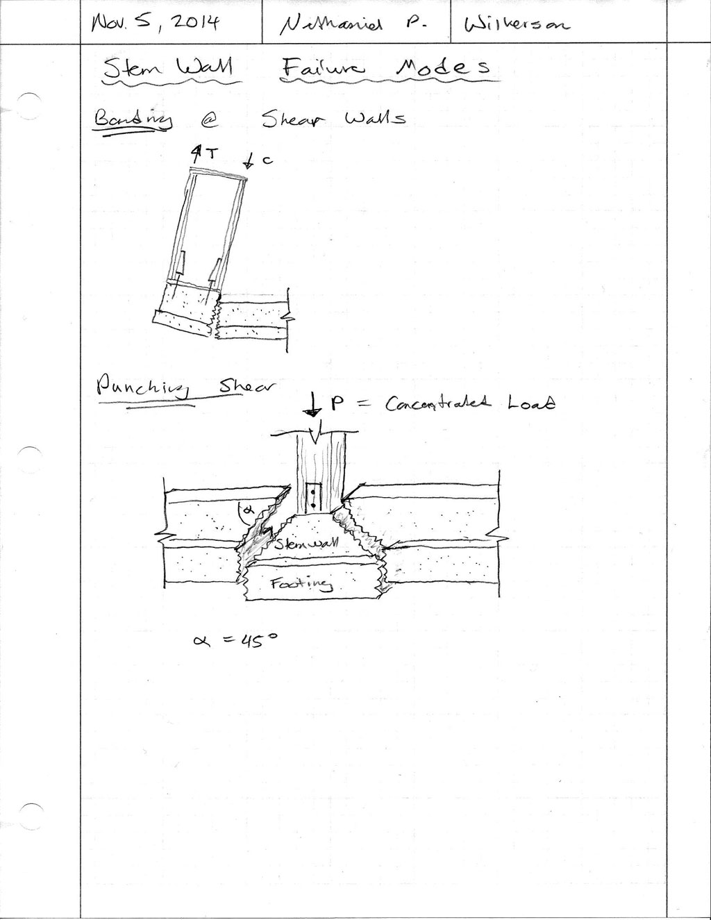
With the footings isn't the big concern with bending due to the moments that the Simpson walls will exert on the foundation and not so much the compression? The foundation will tend to break due to flexure where the Simpson wall meets the window.

CONCRETE_FAILURE_MODES_1024.jpg


However, with the columns (P8) I can see the need for pad footings, especially if my cont. footing were to remain at the 12" wide, 6" deep footing that is called out for the rest of the structure. If this were the case then a 24"x24"x12" pad footing at these two locations would probably be suitable.

A confused student is a good student.
 
You need to check footing capacity for bending...both tension and compression. You also need to make sure your footing is large enough to support the compression loads.

For the wind loads, my opinion is you are making it way too complicated for the size of house you are dealing with. I have used the simplified procedure on homes from 2,000 sqft to 14,000 sqft and many much more complicated than this one. Is it 100% accurate? No, but it works. You are going to spend a lot of time to get close to the same results. Just my opinion.
 
Medeek said:
With the footings isn't the big concern with bending due to the moments that the Simpson walls will exert on the foundation and not so much the compression? The foundation will tend to break due to flexure where the Simpson wall meets the window.

Yes. However, I believe that the flexure issue presents itself more critically as the anchorage issue shown in detail C below. This is the classic opening/closing joint problem in concrete. Hopefully your flexural bars wind up just being a couple of manageable, small diameter bars.

11cdtaq.jpg

egbk0w.jpg

91aznp.jpg

2ly2078.jpg


I like to debate structural engineering theory -- a lot. If I challenge you on something, know that I'm doing so because I respect your opinion enough to either change it or adopt it.
 
This just got more complicated. I need to take some time to digest the concrete detailing suggested above and read a chapter in Malone's book on Shearwall Foundation Issues (Chapter 9.9).

A confused student is a good student.
 
Eh, don't let me freak you out. I'm sure that there will be dissenting opinions. This is just the first question that pops into my head whenever I see those EZ-Bake shear walls. They always seem to be at the far ends of stem walls and/or mounted on flimsy little upstands.

I botched the right hand side crack in my first sketch above. See below for a revision and some supplementary info.

1znnc6r.jpg

2lwouqc.jpg


I like to debate structural engineering theory -- a lot. If I challenge you on something, know that I'm doing so because I respect your opinion enough to either change it or adopt it.
 
I love basements... All your shallow wall worrying is exactly what I had to do on pretty much every job in NZ. Very rare to have basements.

Listen to Kootk. He's bang on with this one!
 
Status
Not open for further replies.

Part and Inventory Search

Sponsor