Tek-Tips is the largest IT community on the Internet today!

Members share and learn making Tek-Tips Forums the best source of peer-reviewed technical information on the Internet!

  • Congratulations TugboatEng on being selected by the Eng-Tips community for having the most helpful posts in the forums last week. Way to Go!

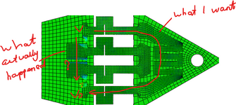
Why does the electrical potential not go the way I wanted?

Zivy98

Materials
Joined
May 27, 2024
Messages
2
Location
DE
Hello guys, I do not understand why the potential does not go along the U shape? It seems that it jumped over the space from one structure to another. This is very confusing, I attached a pic if it helps. Thank you in advance.

Screenshot 2025-07-05.png
 
Can you provide more details ? What are the boundary conditions ? What materials are used for each region ? How are the regions connected (any tie constraints or electrical contact) ?
 
Can you provide more details ? What are the boundary conditions ? What materials are used for each region ? How are the regions connected (any tie constraints or electrical contact) ?
Hi, thank you for your reply. The problem is already solved. The problem was that I defined the electrical conductivity of the board. I wish you a nice weekend!
 
The problem was that I defined the electrical conductivity of the board.
If you don't want the electrical potential to transfer from the circuit to the plate, you can also disable that DOF in tie constraint:

Code:
*TIE, NO ELECTRIC POTENTIAL

This way the tie constraint will only provide mechanical (and thermal if applicable) connection.
 

Part and Inventory Search

Sponsor

Back
Top