Eng-Tips is the largest forum for Engineering Professionals on the Internet.

Members share and learn making Eng-Tips Forums the best source of engineering information on the Internet!

  • Congratulations dmapguru on being selected by the Eng-Tips community for having the most helpful posts in the forums last week. Way to Go!

Why are the Miata front UCA pivot axes tilted inward? 1

NoahLKatz

Mechanical
Joined
Jun 24, 2016
Messages
57
Location
US
I'm looking at using the nice aluminum front control arms from an NC or ND Miata for my reverse trike.

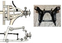
I'm not sure if they've kept geometry similar to the NB Miata front suspension pictured below (the only Miata suspension 3D model I could find), but in any case the UCA's axes are tilted inward by about 2 1/2 deg.

I'm sure the Mazda engineers had a good reason for doing this, but what is it?

The arms are also tilted about the transverse axis about 4 1/2 deg for anti-dive, which besides doing that also seems nice in that it counteracts loss of caster from the remaining nose dive, But the semi-trailing component does the opposite.

Besides that, is a paltry 2 1/2 deg worth the extra frame construction complexity?
Miata_UCA.jpg
 
Building in that angle doesn't change complexity at all. The angle gets built into the design of the stampings, and the stamping tool(s) won't care.

The angle is there because some suspension engineer at Mazda went through an optimisation routine for how they wanted the antidive and the caster to change with suspension travel to achieve whatever objectives they set for themselves, and this is what the optimisation routine spat out. Lots of modern suspension designs have pivot axes at all sorts of 3-D angles which are tough to analyse with pencil and paper, but nowadays it isn't done with pencil and paper, it's done in 3-D models.

If you're re-using parts, presumably you're using your own chassis attachment points. There's no need to maintain Mazda's angles as long as whatever you do, doesn't cause binding or other such troubles. Re-running Mazda's optimisation routine but customised for your own vehicle would probably result in different recommendations for which way the pivot axes go ... but I'm thinking you don't have that!

I wouldn't worry too much about it. Get it somewhere close, and build in some adjustment.
 
> There's no need to maintain Mazda's angles as long as whatever you do, doesn't cause binding or other such troubles.

Glad to hear that, thanks for explaining.

> presumably you're using your own chassis attachment points.

Yes, which is why it does change the complexity; it either adds angles to frame tubes, or results in an asymmetric mounting bracket.
 
Aye, I was thinking about complexity from Mazda's point of view, and you're thinking about it from yours. I would be tempted to use a shimmed mount for the upper control arm so that you can have adjustable caster (via shimming the UCA mounts unequally front to rear).

And then there are things like this ... https://www.fulltiltstreetrods.com/front-suspension-intro.html

(and there are many other sources)
 
> I would be tempted to use a shimmed mount for the upper control arm so that you can have adjustable caster (via shimming the UCA mounts unequally front to rear).

The Miata has caster/camber adjustmet via eccentric bolts on the (L-shaped) LCA chassis mounting points, but I think it's just a couple of degrees.

I could add more by making the UCA chassis clevises wider and filling the gaps with different thickness spacers.

> And then there are things like this ... https://www.fulltiltstreetrods.com/front-suspension-intro.html

The trouble with those is that they're pricey and overweight for my project, a V-twin powered reverse trike that I expect to weigh about 1000 pounds.
 
> Building in that angle doesn't change complexity at all. The angle gets built into the design of the stampings, and the stamping tool(s) won't care.

So are stamping dies now made with CNC, and tool and die makers are an extinct species?
 
> Building in that angle doesn't change complexity at all. The angle gets built into the design of the stampings, and the stamping tool(s) won't care.

So are stamping dies now made with CNC, and tool and die makers are an extinct species?

Yes, on the CNC (and that's been the case for a couple of decades). Still need people with tool and die experience to get them right ...

Can-Am Spyder front suspension https://www.pieces-can-am.fr/canam-moto/SPYDER/2023/SPYDER-RT/05-Suspension--Front/4855/29/0/4855

Looks from the diagram like they have anti-dive geometry built in. Friend of mine has one. I'll see about taking a look at it.
 
So now I think that the Mazda engineers might have in fact done the simplest thing.

I noticed when working on the chassis design that with the UCA's mounted on angled upright members (as is the Mazda subframe), the tilt for anti-dive causes the arms' chassis pickup points to have slightly different transverse locations; see pic's.

That gives them a 1.7 deg rotation about the Z axis, which to remove would require unique and lopsided clevis brackets.

I'd rather not fuss with that, so I'll assume there will be no ill effects unless someone thinks otherwise.
 

Attachments

  • uca.jpg
    uca.jpg
    114 KB · Views: 13
Are the upper control arm chassis pick up points stuck on the loop made from a short top rail and two longer angled legs cantilevered from the single square tube lower rail ?
I'm thinking frontal wheel impact absorption may mostly result from the square tubing loop and the lower rail sacrificing themselves.
 
My pet example for a suspension with insane axes for the suspension is the Mustang Cobra IRS. My ear drums glazed over when the rationale for those choices was made. I can see why you might some castor change in pitch, to retain your geometry under braking, and OK I know anti/pro dive and to a much lesser extent pro squat are handy.
 
Last edited:
Are the upper control arm chassis pick up points stuck on the loop made from a short top rail and two longer angled legs cantilevered from the single square tube lower rail ?

By "stuck" I don't know if you mean did I stick them there, or do they have to stay there, but it's the former.

This was the very first attempt to connect the control arms to some structure, and it will most certainly not stay that way.

As for your comment about impact absorption, that will be taken by the soft bushing at the bottom (front of car).

I've spun the lower control arms and steering about the Z axis because that makes it easier to put the engine I where I want it.

This changes it to rear steering and along with new steering arms will let me control Ackerman; my front track is much wider than the Miata's so I don't imagine it's Ackerman would work for me.
 
Other than "they're pretty", what's the motivation to use the Miata parts?

Project cars have a long tradition of welded tube A-arms, and you can make whatever geometry you need.
 
Actually I think tubular A-arms are nicer looking, and is what I started designing with.

Then I learned about the benefits of L-arms in reducing impact harshness, while retaining good handling.

Also they're a quite lightweight, ready-to-go solution, saving fabrication time, and have caster and camber adjustment by eccentrics at the LCA pickup points.
 
Last edited:

Part and Inventory Search

Sponsor

Back
Top