Continue to Site

Eng-Tips is the largest engineering community on the Internet

Intelligent Work Forums for Engineering Professionals

  • Congratulations waross on being selected by the Eng-Tips community for having the most helpful posts in the forums last week. Way to Go!

What's your approach for tolerancing concentricity of a polygon, see attached image 2

Status
Not open for further replies.

Perka

Automotive
Feb 26, 2019
8
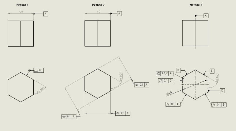
I'm new to GD&T. What's your approach of tolerancing a polygon shape.

'Profile of a surface' as in option 1 locks down a lot.

At first I thought it looked down too much so I tried Method 2 using symmetry, which in the end pretty much did the same as profile of a surface.

Then I thought of some dotted inscribed reference circle with concentricity tolerance, along with parallellism tolerance.

Brain is confused to say the least. Suggestions?

polygon_tolerancing_approach_kytep2.png
 
Replies continue below

Recommended for you

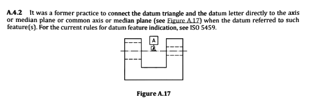
Dimension according to ISO 129 and GD&T according to ISO 1101

from ISO 1101
gdt_datum_feature_on_axis_no_longer_n4mkm5.png
 
This is probably where part of us, me included, have to "cede the floor" for those who are knowledgeable in ISO.
I will only allow myself to add that for the ISO case, my comment about Position vs. Symmetry is probably not relevant. You can probably keep the symmetry control because one of the few things I know about ISO is that ISO Symmetry is a special case of Position and is widely used (unless that too is not up to date - but not likely).
 
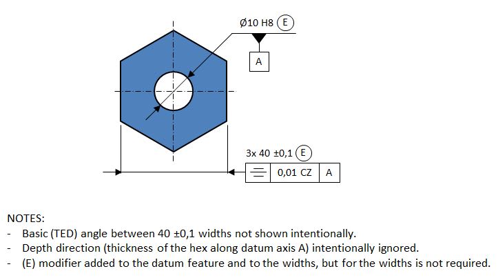
Knowing it's ISO, this is how I would do it with the symmetry approach:

hex_ISO_mrdfrh.jpg


As it was mentioned, symmetry can be used here without any ASME-related issues because in ISO it's just a special case position tolerance. What is important is the CZ (combined zone) modifier that ties the 3 symmetry tolerance zones together in terms of mutual basic orientation. Without it the tolerance zones would be totally unclocked to each other. This is the consequence of default independency principle in ISO that doesn't exist in ASME.

Also, as shown, circle E modifier (envelope requirement) is not a must for the widths, but most likely is required for the datum feature A - without it, form of the hole is totally out of control. Again this is the consequence of the defualt independency principle in ISO. In ASME, form of the hole would be controlled within the size tolerance through Rule #1.

Additionally, tolerance value and datum reference A in the symmetry tolerance indicator could technically be referenced at MMR (Maximum Material Requirement) or LMR (Least Material Requirement) by using circle M or circle L modifier after the letter A, because in ISO, unlike in ASME, it is not prohibited to use M or L modifiers for the tolerance value and the datum letter in a symmetry or concentricity tolerance (but then the use of circle E modifiers for the widths and the datum hole would become questionable at best).

Side note: From ISO vs. ASME comparison perspective even more interesting would be talking about approach #1 (profile all around), because it would show even more differences between the two systems. Unfortunately, for now that's all I am able to say about it and I can't promise I will find some time to prepare some sketches showing what I mean.
 
pmarc,
Does the Actual Mating Envelope principle exist in ISO and does it play the role that it plays in ASME Position in both ISO Position and Symmetry?
 
By default, ISO Position, Symmetry and Coaxiality (concentricity applied to a 3D feature) don't use the concept of Actual Mating Envelope. These three tolerances control imperfect derived features (extracted median line, extracted median plane) which aren't derived from feature's AME.

There are modifiers - different for internal and external feature of size - that are able to change the type of controlled derived feature from imperfect (extracted median line, extracted median plane) to perfect (axis, center plane) derived from ASME-like mating envelopes, but they can only be used if the tolerance value in the position, symmetry or coaxiality tolerance indicator is specified RFS. That is because in ISO there is no axis / center plane interpretation for tolerances specified at MMR (or LMR) basis.
 
Thanks pmarc, that is very interesting.
Those "extracted" median lines and median planes must be derived differently than ASME median lines and median planes. Per ASME, the UAME of the feature is involved in the definition of these elements (center points are sampled at cross sections perpendicular to the axis / center plane of the AME...) I suppose that this is the main difference between ASME and ISO Symmetry - the method by which the controlled median plane is derived. Is that right?

I hope the OP doesn't mind the side topic evolving here...
 
pmarc said:
From ISO vs. ASME comparison perspective even more interesting would be talking about approach #1 (profile all around), because it would show even more differences between the two systems. Unfortunately, for now that's all I am able to say about it and I can't promise I will find some time to prepare some sketches showing what I mean.

I know pmarc wouldn’t open up this subject if he was not willing to help us with the full understanding of the details (differences between the two systems)
I am willing to “help” moving this subject (of the differences) just a little bit forward by posting these two attachments (profile ASME versus profile ISO) I found here on the forum. Not sure who should I give credit to....

I just hope pmarc will come back and clarify if I am on a right track (profile all around differences) or he was talking about something else.
 
 https://files.engineering.com/getfile.aspx?folder=6a48bb7a-30a0-4483-bf50-e3adead41b49&file=Profile_ISO_-_ASME_.PNG
I'm very interested to learn about the differences in profile between the two standards - thanks pmarc for noting it and greenimi for posting the attachment. FYI greenimi - if you're looking for credit that looks almost like something by tec-ease, looks very similar to their other materials but I could be wrong.

In regards to the attachment posted by greenimi, I see that the example says to imagine "dragging the center point of a 4mm sphere around the true profile". Not to nitpick, but I have to imagine that a better analog would actually be a 4mm cylinder, not a sphere - unless the treatment of profile is that radically different.
 
Sem,

As I said I don't know too much about ISO, but from what I've read I seemed to get the impression that ISO does not deal much with mating envelopes of the types so commonly utilized in the ASME standard. From what I gathered typically ISO relies on envelopes which are usually some sort of averaging which don't necessarily reflect the mating conditions of the features whereas ASME mating envelopes involve the extreme points of the features involved, which would actually contact when mated together. Now I guess which one is actually more representative due to deformation when mating might be another topic.

pmarc 28 Feb 19 05:34 said:
There are modifiers - different for internal and external feature of size - that are able to change the type of controlled derived feature from imperfect (extracted median line, extracted median plane) to perfect (axis, center plane) derived from ASME-like mating envelopes, but they can only be used if the tolerance value in the position, symmetry or coaxiality tolerance indicator is specified RFS.

pmarc - are these similar analogs or identical?
 
Thanks chez311.
The "averaging envelopes" practice that ISO seems to require sounds less friendly for physical gauging and datum simulation.
 
Sem_D220 said:
Those "extracted" median lines and median planes must be derived differently than ASME median lines and median planes. Per ASME, the UAME of the feature is involved in the definition of these elements (center points are sampled at cross sections perpendicular to the axis / center plane of the AME...) I suppose that this is the main difference between ASME and ISO Symmetry - the method by which the controlled median plane is derived. Is that right?

Yes, that is right. In ISO, LSQ (least sum of squares) features, and not minimum circumsribed or maximum inscribed features, are involved in the definition of the extracted median plane and line.

chez311 said:
pmarc - are these similar analogs or identical?

The modifiers I mentioned basically change an element controlled with a geometric tolerance, like position, symmetry or coaxiality.

For example, circle X modifier used in a position tolerance frame applied to a hole changes default controlled element from imperfect extracted median line to a perfect axis of the maximum possible cylinder expanded within the hole. So it defines the same requirement as position callout in ASME.

Circle N modifier used in a position tolerance frame applied to a pin changes default controlled element from imperfect extracted median line to a perfect axis of the minimum possible cylinder contracted about the pin. So again, it defines the same requirement as position in ASME.

greenimi said:
I just hope pmarc will come back and clarify if I am on a right track (profile all around differences) or he was talking about something else.

Your attachment refers to an outdated ISO standard for profile tolerancing. This is what I meant:

First, I hope it's clear. Second, I hope that even without trying to understand the content of the document, it sufficiently shows how different both systems are. And third, I hope that those who believed otherwise will at least consider changing their mind.

EDIT: Link edited - the document attached originally contained too many pages.
 
Thanks, pmarc!
That is a very informative review of the different Profile applications by ISO.
Lots of modifiers. Looks like they are on a mission to standardize every design intent ever possible. I don't know if it's good or bad, but it certainly sparks an interest to get more familiar with their set of GD&T standards.
 
That’s why I came here often. Time well spent for education. Thank you again pmarc.

I am trying to learn ISO as much as possible. Or, at least, the main differences between ISO and ASME.
Looks like the profile section is very different despite the “rumors” (and I get a lot of less than educated opinions at my work place that the systems --ASME and ISO---are almost the same or the converging time is near). Nothing further from the truth.
Thanks again for your excellent piece of work.


pmarc said:
Additionally, tolerance value and datum reference A in the symmetry tolerance indicator could technically be referenced at MMR (Maximum Material Requirement) or LMR (Least Material Requirement) by using circle M or circle L modifier after the letter A, because in ISO, unlike in ASME, it is not prohibited to use M or L modifiers for the tolerance value and the datum letter in a symmetry or concentricity tolerance (but then the use of circle E modifiers for the widths and the datum hole would become questionable at best).

Pmarc,

I self-admitted I don’t have much knowledge in ISO (but I am learning) so I might want to ask you some quick questions about ISO concepts, hopefully easy: “yes-no-maybe” questions.
Are you saying that for a feature of size definition “a combo” size with E + position modified at MMR is an invalid callout?
If a FOS is used as a datum feature and modified at MMR in other FCF’s, then its size cannot be used with E symbol?

Looks like the straightness of a FOS must be refinement of the position, symmetry, coaxiality if the case of this combo of geometric tolerances are applied to the same feature (straightness-position, straightness-symmetry, straightness-coaxiality/concentricity). Is my understanding correct?


Thank you for your answers and, as usually, I appreciate for input and contribution on this forum.
 
greenimi said:
Are you saying that for a feature of size definition “a combo” size with E + position modified at MMR is an invalid callout?

No, I didn't say that, but it is hard to disagree with the following statement from ISO 2692:2014:
"Use of the envelope requirement (E) (previously also known as the Taylor Principle) [in conjuction with a geometric tolerance at MMR] usually leads to superfluous constraints regarding the function of the feature(s) (assembleability). Use of such constraints and size definitions reduces the technical and economic advantage of maximum material requirement, MMR."

greenimi said:
If a FOS is used as a datum feature and modified at MMR in other FCF’s, then its size cannot be used with E symbol?

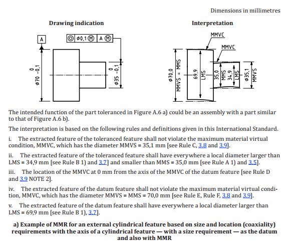
If a FOS is controlled with a size tolerance only and then is referenced at MMR in the datum portion of a geometric tolerance, for some reason ISO says that maximum material virtual size is equal to the MMS size of the feature. See a snapshot from ISO 2692:2014 below:
iso_2692_2014_qasnk8.jpg


This means that in such case the envelope requirement is imposed to the datum feature even though the envelope requirement has not been explicitly specified on the face of the drawing. To me this rule is a gap in their logic, and I know from the discussion with Henrik Nielsen, former chairman of ISO TC 213, that they have been working on changing that.

greenimi said:
Looks like the straightness of a FOS must be refinement of the position, symmetry, coaxiality if the case of this combo of geometric tolerances are applied to the same feature (straightness-position, straightness-symmetry, straightness-coaxiality/concentricity). Is my understanding correct?

Yes, that is true. In ASME this is also true but only because Y14.5 aribirtarly says so. From theoretical point of view it wouldn't have to be.
 
Thank you pmarc for your answers.

What does not seem to me very intuitive is that even when E is used for a FOS dimension, the form tolerance can be bigger than the size tolerance on an ISO drawing.
Lack of my education in ISO and lack of full understanding of the default Independency principle makes this concept hard to grasp.

So, the straightness (one of the form possible errors) must be refinement, but circularity (or cylindricity) does not.

Do you know, by any chance, which ISO standard has this form/ size/ location relationship explained?
I am just trying to train myself to think in ISO world, with no much success (so far).
 
greenimi said:
What does not seem to me very intuitive is that even when E is used for a FOS dimension, the form tolerance can be bigger than the size tolerance on an ISO drawing.

[...]

So, the straightness (one of the form possible errors) must be refinement, but circularity (or cylindricity) does not.

Not sure what makes you think that. Could you clarify?
 
Thank you again for engaging.
So, if a feature of size specified on an ISO GPS defined drawing has the envelope E symbol associated with its size dimension, then how it is possible to have cylindricity bigger than the size tolerance?
Ø 14 -0.016 / -0.034 E
Cylindricity 0.05
Coaxiality Ø0.05 to a DRF

Now, if a straightness of that FOS is added, that specific tolerance straightness value should be smaller than the coaxiality Ø0.05 value?

Am I missing something?

Which of my statement(s), from this post or the previous one, is not true? (and I am not pretending that all are)
 
For the given size callout and with the envelope princile in charge, I don't think cylindricity tolerance of 0.05 makes sense. I know it was taken directly from Nielsen's handbook, but in my opinion this is a mistake.
 
Okay. Thank you pmarc
So, looks like I was not too far away in the weeds, or questioning it.
In general, when I am learning, I have to start from something that I assume is a correct baseline. If I start to query everything, probably I just go nowhere.

Maybe Mr Nielsen thinks in terms of the tolerances cannot "see each other" (same as discussed here: ...Me.... trying to justify

I would say it is bad enough that the official ISO GPS has over 100's standards, but is even worse when the commercial books (books designed/written to "translate" heavy technical language in simple terms) have mistakes to this level.
Really confusing.

I might have more questions related with the subject, but for today I already abused you enough. (and I don't want you to get mad:) [bow])
 
Status
Not open for further replies.

Part and Inventory Search

Sponsor