Continue to Site

Eng-Tips is the largest engineering community on the Internet

Intelligent Work Forums for Engineering Professionals

  • Congratulations waross on being selected by the Eng-Tips community for having the most helpful posts in the forums last week. Way to Go!

What's your approach for tolerancing concentricity of a polygon, see attached image 2

Status
Not open for further replies.

Perka

Automotive
Feb 26, 2019
8
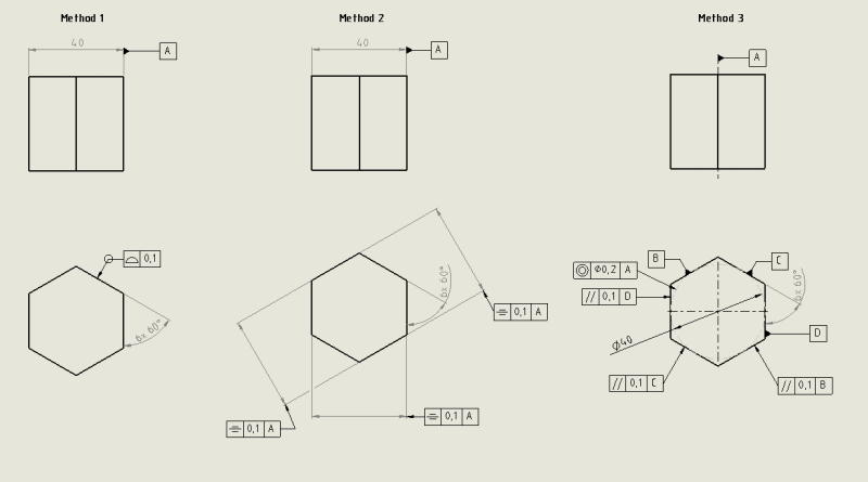
I'm new to GD&T. What's your approach of tolerancing a polygon shape.

'Profile of a surface' as in option 1 locks down a lot.

At first I thought it looked down too much so I tried Method 2 using symmetry, which in the end pretty much did the same as profile of a surface.

Then I thought of some dotted inscribed reference circle with concentricity tolerance, along with parallellism tolerance.

Brain is confused to say the least. Suggestions?

polygon_tolerancing_approach_kytep2.png
 
Replies continue below

Recommended for you

Pmarc,

I hope you are still around as I have quick follow up questions. (As I promised yesterday I did not ask my follow up questions as I did not want to stretch too much your patience)

If yesterday’s feature of size: Ø 14 -0.016 / -0.034 , does not have the envelope E (and also the drawing does not specify ISO 2768) am I correct in saying that Cylindricity within 0.05 (cylindricity size bigger than the tolerance size) and Coaxiality Ø0.05 (RFS or MMR) to a DRF “combo” makes logical sense?

In other words, I am trying to find what requirements (form allowances or location errors) interfere with each other in ISO world.

Combo 1: size + cylindricity>size + coaxiality (RFS) > size
Combo 2: size+ cylindricity> size + coaxiality (MMR) > size

Thanks again for your input


greenimi said:
If yesterday’s feature of size: Ø 14 -0.016 / -0.034 , does not have the envelope E (and also the drawing does not specify ISO 2768) am I correct in saying that Cylindricity within 0.05 (cylindricity size bigger than the tolerance size) and Coaxiality Ø0.05 (RFS or MMR) to a DRF “combo” makes logical sense?

Yes, I would say this is legal combination of callouts in ISO.

greenimi said:
In other words, I am trying to find what requirements (form allowances or location errors) interfere with each other in ISO world.

Combo 1: size + cylindricity>size + coaxiality (RFS) > size
Combo 2: size+ cylindricity> size + coaxiality (MMR) > size

Sorry, but I am not sure I understand this question.
 
pmarc said:
Quote (greenimi)

In other words, I am trying to find what requirements (form allowances or location errors) interfere with each other in ISO world.

Combo 1: size + cylindricity>size + coaxiality (RFS) > size
Combo 2: size+ cylindricity> size + coaxiality (MMR) > size


Sorry, but I am not sure I understand this question.


Pmarc,

I was questioning the relationship between (of lack thereof) of cylindricity and coaxiality in ISO (coaxiality either at RFS, either modified at MMR).
As far as I understood from this discussion (and other threads here on the forum) when straightness of a FOS (straightness of the axis) is used in ISO, its tolerance value shall be smaller than the coaxiality (shall be refinement) regardless if the coaxiality is RFS or MMR.

But straightness is just one of the possible form errors and I was just inquiring about the other possible form error (in the other direction) such as cylindricity (maybe even circularity)
Looks like, you just confirmed that for cylindricity / circularity is not such a requirement in ISO GPS to be a refinement (to be smaller than coaxiality tolerance).

Is my understanding correct now or I am still missing the ISO concept of defining FOS's?

Thanks again


greenimi said:
Looks like, you just confirmed that for cylindricity / circularity is not such a requirement in ISO GPS to be a refinement (to be smaller than coaxiality tolerance).

Yes, that is correct.
 
ISO_uizd7t.png


Pmarc,

I have prints showing those ISO combinations. Now, knowing that ISO 2692 is invoked (as being an ISO drawing that is calling 8015) should I understand that:

- any linear sizes will have their envelope concept by default also invoked.

- there should be no coaxiality (concentricity, symmetry) callouts modified at MMR or LMR (at least per the theory specified in ISO2692).
 
Kedu said:
- any linear sizes will have their envelope concept by default also invoked.
Yes, that is true.

Kedu said:
- there should be no coaxiality (concentricity, symmetry) callouts modified at MMR or LMR (at least per the theory specified in ISO2692).
ISO 2692 says that: "Use of the envelope requirement (E) (previously also known as the Taylor Principle) [in conjuction with a geometric tolerance at MMR] usually leads to superfluous constraints regarding the function of the feature(s) (assembleability). Use of such constraints and size definitions reduces the technical and economic advantage of maximum material requirement, MMR."

This means that according to the standard, when applying a geometrical tolerance at MMR, (E) modifier should not rather be used, as it "reduces the technical and economic advantage of maximum material requirement".
 
May I force one more question: how ISO allows some linear sizes to take exception of the envelope requirement on prints shown with notes as such (previous posted picture) in order to use MMR/LMR?
Do we have to put E near other linear sizes? (And get rid of the general note E). Or there are other ways around it?
 
ISO 14405-1 defines LP modifier (two-point size) that, when applied to the size specification, basically cancels the default envelope requirement for particular size dimension in cases like yours, and makes the independency principle in charge again.

lp_grpbxy.jpg


But I would like to repeat: ISO does not prohibit use of (E) modifier for features controlled at MMR. They just say that this combination isn't good idea from technical and economic perspective.
 
Pmarc,
Thank you for the info. Really helpful and enlightening discussion.


Status
Not open for further replies.

Part and Inventory Search

Sponsor