Thanks Hallec, chez311 and SEM_D220. Lots of great response at this forum, glad I registered
![[bigears]](/data/assets/smilies/bigears.gif "[bigears] [bigears]")
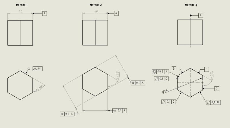
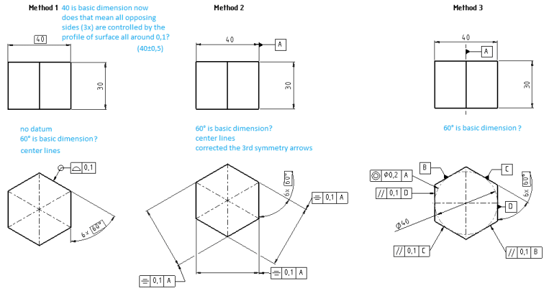
Reason I added center lines on Method 2 was due to symmetry, but then I thought center lines might make method 1 easier to read as well, and wanted to hear your comments on it.
Did not know that
'...the datum feature symbol for concentricity can't be attached to a centerline' (SEM_D220), might have some GD&T documents on my desk I should throw away, cause I'm pretty sure that they used centerline for concentricity datum, along with another example where the datum pointed at the dimension arrows, and said it had the same meaning.
Method 2:
Thanks SEM_D220, I read up on how to measure symmetry and realize that (like you said) two opposing side, where left side look like this ) and right side like this ( They would result in a "vertical line/zero assymetry" if you took some symmetry measurements with the caliper (measuring at different heights along vertical axis with the caliper jaws opening/measuring horizontally.
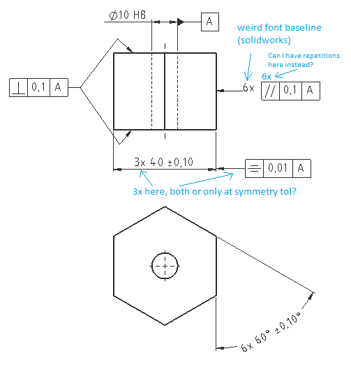
As suggested, remove basic from 60° dimension
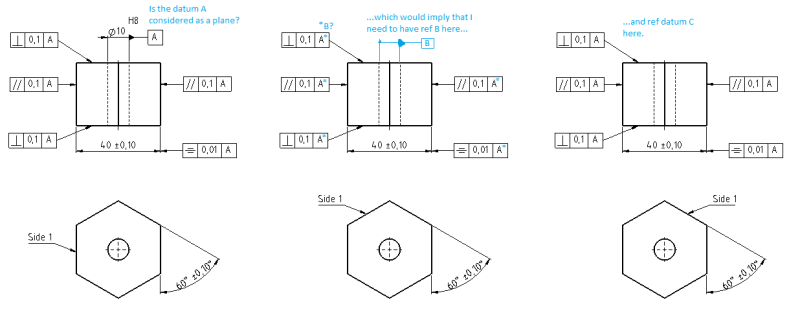
I'd also need to add parallelism to control the form. And from what I've read tonight I have to have the datum feature on a surface (instead of axis) if I want to control form with parallelism, in other words surface parallelism. On the image it was pointing at the 40 dimension arrow (axis in the center of polygon), which would not be correct in this case I believe (lots to learn). Need to figure out if I need surface parallelism or flatness on the faces... hmmm.
Back to symmetry for method 2, how would one go about placing a symmetry datum, is it possible given I only have "one shape/feature, extruded polygon"?
SEM_D220 said:
The datum features for symmetry can't be the controlled features themselves, ...
*edited Good quote that I will try to remember from now on
")
chez311 said:
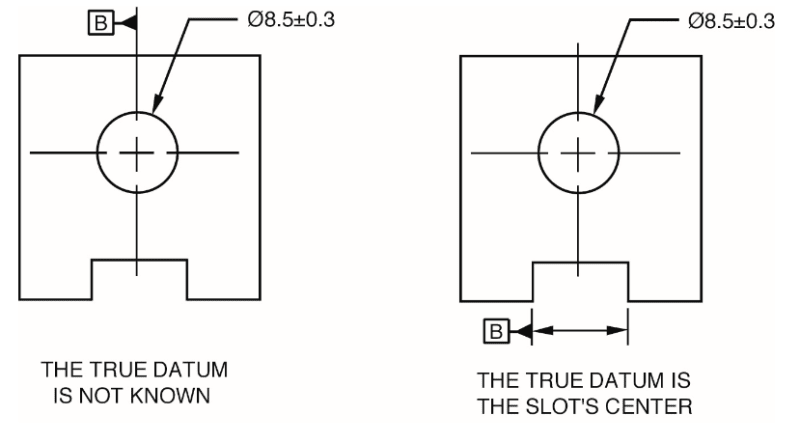
What you need to remember is that datums are derived from,and controls are applied to, actual physical features - its a common error for example to define a width dimension and then attach a datum reference to the center line between that width because the desire is to define a datum center plane between this width, this is NOT allowed. The datum reference is applied to the width dimension/leader lines and by the rules in the standard it defines a center plane.
![[smile]](/data/assets/smilies/smile.gif "[smile] [smile]")