Continue to Site

Eng-Tips is the largest engineering community on the Internet

Intelligent Work Forums for Engineering Professionals

  • Congratulations 3DDave on being selected by the Eng-Tips community for having the most helpful posts in the forums last week. Way to Go!

What is the correct way of setting up this problem ?

Status
Not open for further replies.

Milos Stancic

Mechanical
Feb 1, 2022
9
Hello everyone,

This is my first time posting, so forgive me if I did it in the wrong sub thread or wrong forum.

I have a very specific problem that I though I have solution to, but then after talking to my colleague and understanding his point of view I am left a bit puzzled now.

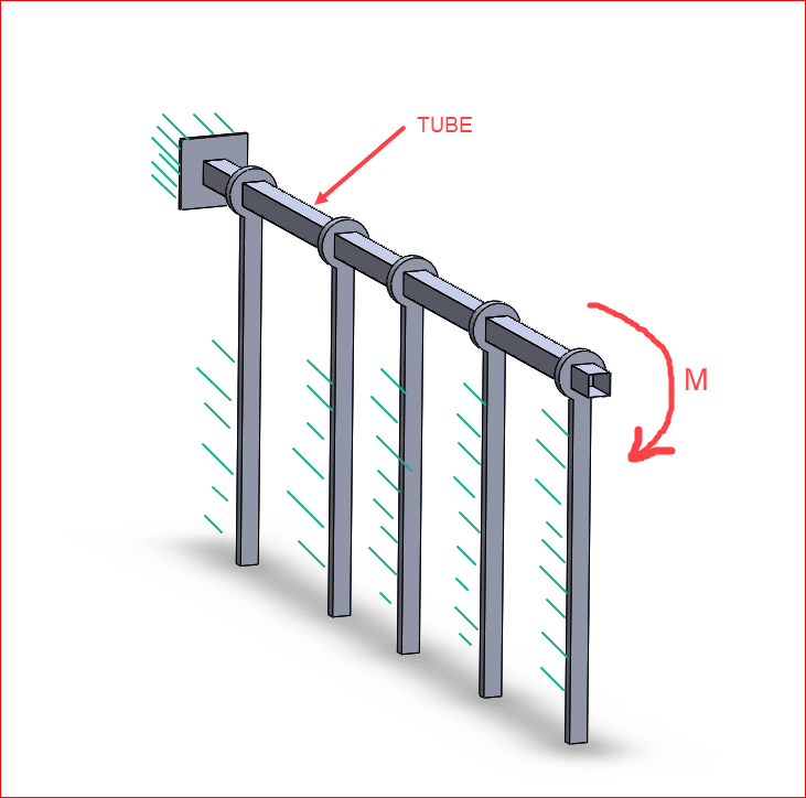
Here's the setup (I also uploaded a screenshot of it for more clarity):

I have a square tube that is fixed on one end (left end on the picture). The square tube is being supported by I beam piles that have bearings on top. So this allows the square tubing to rotate around it's axis.

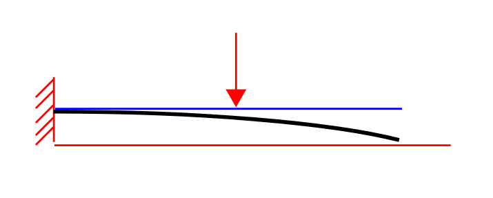
The square tubing gets a moment loading at the end of the tube. We know what that moment is and we know that it creates a 30 degree deflection at the end of the tube (torsional deflection).

For design purposes and interference with some other parts of design we don't want this tube to rotate that much. We want to allow it to rotate 15 degrees only. So we designed a hard stop at the end. It allows the torque tube to rotate 15 degrees and when the moment gets too high it hits the hard stop that doesn't allow it to rotate more than 15 degrees at the end.

NOW this is the question. How much load does that hard stop takes ?

For the sake of argument let's assume that it takes 1000 KNm to torsionally deflect the tube to 30 degrees at the end of it. At 500 KNm it gets to 15 degrees and hits the hard stop. The torque keeps being applied to 1000 KNm. Does hard stop sees full load divided /2 (half of the full load on left fixed point and half of the load on the new fixed point (the hard stop)) or is load divided 75% for the fixed point to the left and 25% for the new fixed point ton the right (the hard stop) ? My colleague says that new hard stop doesn't see any of the first 500KNm load because the tube is not yet engaged, and once it gets engaged that's when it starts seeing the load, but only other 500KNm are being shared between the fixed points, not total load. Hence 75% to 25% distribution.

Thanks for helping out and sorry if this sounds confusing. I will do my best to explain it better if needed.
 
Replies continue below

Recommended for you

No picture was attached. If it's fixed at one end, and both the moment and the hard stop are at the other end, I'd go with your colleague's numbers, that 500knm goes into the fixed end, then once it hits the hard stop, all the remaining moment goes into the hard stop.
If the moment is applied at some intermediate point or if the hard stop is at some intermediate point, I'd have to give it more thought.
In real life, you might have substantial impact loads that overwhelm the static loading assumptions.
 
Hi @JStephen,

Thanks for responding.

I think I attached the picture now. Let me know if it's not there.

The hard stop is at the end.

The only thing that is confusing me is that we have a constant load. The torque doesn't stop for hours and hours. So, in my head, it doesn't matter when it got engaged to the hard stop it's still going to get that max load eventually.

But I can also see his perspective and his (and yours train of thought). Is there some equation or a way to prove this without having doubts ?

Thanks again for replying.
 
You need to paste the link into your post. There's one button to upload it and a separate one to paste the link or you can copy and paste it yourself.
 
I don't understand the 50-50 or 75-25 distribution.
The tube's fixed end will resist all of the load applied up until it twists 15° and the hard stop is engaged. At this point, if the hard stop is essentially rigid compared to the tube (and it must be if it doesn't allow the tube to twist any more), the hard stop will take all additional load that is applied to the tube, the fixed end of the tube will not see any additional load at that point.
 
Hi @dauwerda,

I apologize for the confusion. I didn't explain well. The moment is actually constant throughout whole square tube. It is not applied at the end only.
 
Okay, so essentially it is fixed at one end until the tube rotates 15° then a hard stop engages and it is essentially fixed at both ends.

The force required to rotate to 15° would all go into the fixed end, after that the moment would be resisted by both ends, assuming the torque is applied evenly along the length, or in the middle, this would result in the additional load being shared by each end equally. So your 75-25 scenario.
 
If the four supports at the left allow free rotation of the HSS, then I agree with dauwerda. But the diagram does not appear to indicate free rotation. The HSS looks as if it is clamped at every support.

Milos Stancic said:
I apologize for the confusion. I didn't explain well. The moment is actually constant throughout whole square tube. It is not applied at the end only.

There is a torsional moment applied at the end only, which means that the torsion is constant over the length of the HSS.

Capture_u3xw7c.png


BA
 
You need double plates at the end, one fixed on the wall with protruding anchors, one fixed to the tube with slotted holes that allow and limit the angle of rotation. Use shear friction bolts and tightened to the desired torque. Once the limit is exceeded, the bolts run into bearing.
 
Hey @BAretired,

Again, my apologies. I sketched this very quickly. Those circular items are bearings. The square tube can rotate freely inside those bearings.

@duawerda made a correct assumption of how the system functions. One end is fixed, the other end rotates 15 degrees and after that it hits the hard stop, and there is 15 more degrees of load applied to the tube evenly.

Thank you all for helping me with this.

I do have one question now. Why is the load spread 75-25 ? why not 50 - 50 ? I understand the logic behind 75 - 25, what I am wondering is why isn't the full load applied to both fixed points ? Why does it matter when it got engaged ?

Thank you.
 
so the tube is free to rotate on those four "supports".

so the tube twists (due to a torque applied at the end) 15deg at the end, and 7.5deg at the mid-span.

then the tube hits a hard stop and doesn't rotate any more. ok.
but how does the hard stop react the applied torque ?
does the first support provide this restraint ? and so does it bend under this load ?
does the tube bend under this load ??

or does this hard stop load both sides of the tube, like a couple ?
then the tube would sit there, and the support would take the applied torque (couple).

??


another day in paradise, or is paradise one day closer ?
 
I agree with 50-50. Not sure where you get 75-25.

The fixed end feels 500 kN-m and the tube rotates 15 degrees. The hard stop feels nothing until the torque is increased beyond 500 kN-m. As the applied torque is increased, the hard stop becomes a new fixed end and starts to feel a torque. When the torque is increased to 1000kN-m, the hard stop feels 500kN-m from the HSS and 500kN-m from the applied torque, thus satisfying equilibrium (sum of moments = 1000kN-m).

If the applied torque is released, moment going to the hard stop decreases to 500kN-m, which is the same as the torque in the HSS and the fixed end. Rotation of the HSS remains at 15 degrees.

BA
 
Milos Stancic said:
I do have one question now. Why is the load spread 75-25 ? why not 50 - 50 ? I understand the logic behind 75 - 25, what I am wondering is why isn't the full load applied to both fixed points ? Why does it matter when it got engaged ?

Per my understanding above the original fixed end resists all of the applied torque until the free end of the tube rotates 15°. per your numbers, this happens at500 kN-m. Once the tube twists this amount a hard stop engages at the free end and prevents any further twist, essentially becoming a fixed end. Now you have a tube that is twisted 15° from one end to the other with both ends fixed. One end is resisting a torque of 500kN-m and the other end is not resisting any torque.

More torque is then applied to the tube (uniformly across its length). This additional load will be resisted equally by each end due to the equal loading and uniform torsional resistance of the tube. So all additional loading will be distributed with 50% going to each end. Using your additional torque of 500kN-m, one end will resist 250kN-m (for a total of 750kN-m) and the hard stop end will resist the other 250kN-M.

Any additional loading is applied to the ends with a 50% to 50% distribution. The final condition has the original fixed end resisting 750kN-m and the hard stop end resisting 250kN-m which is a total 75%-25% distribution. If your additional load is not equal to you initial load than the 75% to 25% distribution would not hold true.
 
@dauwerda and @BAretired. Hmmmmm interesting point. Let me also ask you this. One of the main purposes of asking everyone this is because we are designing the hard stop. I originally thought that we need to design the hard stop to be able to withstand the full load, all 1000KNm. But one of the engineers here mentioned @dauwerda's approach to this and according to that, the hard stop is seeing only 25KNm of load. But that somehow seems very low to me (even though I understand your logical approach to this). Isn't in the end a total of 1000KNm trying to twist this tube shouldn't it be 500 knm 500knm on both sides ? Why does it matter what happened before ? Is there potential energy stored in the tube ?
 
I agree with @dauwerda's analysis. Just prior to the free end touching the stop, the entire torque is resisted by the fixed end only (100%), the free end resists nothing (0%) but rotates until hitting the stop. Now the tube is supported on both ends, and any torque applied thereafter is distributed to both ends equally (50%/50%), resulting in a 75/25 split.
 
1. 500kN-m is applied to end stop which becomes a fixed end. Both ends feel 500kN-m when applied torque is removed.
2. 500kN-m is applied uniformly over full length of the beam. Both fixed ends feel 250kN-m more (total 750kN-m each, or 50-50 distribution).
3. Uniform torque is removed. Both ends feel 500kN-m, or 50-50 distribution).

BA
 
BA, I'm not following your logic here. Imagine that you have a cantilever that can bottom out. If you apply just enough force to it to close the gap, the entire force will be in the original support. After that, each additional pound is shared by the original support and the new one caused by bottoming out, but the original force is still needed to maintain the contact - if it's removed the gap opens up again

Bottomed_out_cantilever_qvvr5m.png
 
Can't argue with that, chris3eb. But it's not a valid analogy.

Let's say the HSS is fixed at both ends. Beam length is 10 m. A uniform clockwise (CW) torque is applied to the beam of 50kN-m per m, for a total of 500kN-m. Each fixed support resists a CCW torque of 250kN-m. The beam has a torque varying linearly from 0 at midspan to 250 at each end.

In our problem, there is a CW torque of 500kN-m, which causes a 500kN-m torque at the fixed end and zero torque at the end stop. If the end stop becomes a fixed support, both fixed end and end stop must provide a CCW torque of 500kN-m. When the uniform 500 kN-m torque is added, the CCW torque at each end is 750kN-m, while torque at midspan is 500kN-m.


BA
 
Unless the fixed end is a spring, we rotate the free end by a torque then release it, the tube won't rotate back by itself, what is the stress at the free end? Then we place a stop, and apply additional torque, which end will engage to hold the free end (now with a stop) from rotation? I think the superposition method answers this question - the shear diagram of a cantilever plus a beam with both ends restrained for rotation.
 
Status
Not open for further replies.

Part and Inventory Search

Sponsor