Milos Stancic
Mechanical
- Feb 1, 2022
- 9
Hello everyone,
This is my first time posting, so forgive me if I did it in the wrong sub thread or wrong forum.
I have a very specific problem that I though I have solution to, but then after talking to my colleague and understanding his point of view I am left a bit puzzled now.
Here's the setup (I also uploaded a screenshot of it for more clarity):
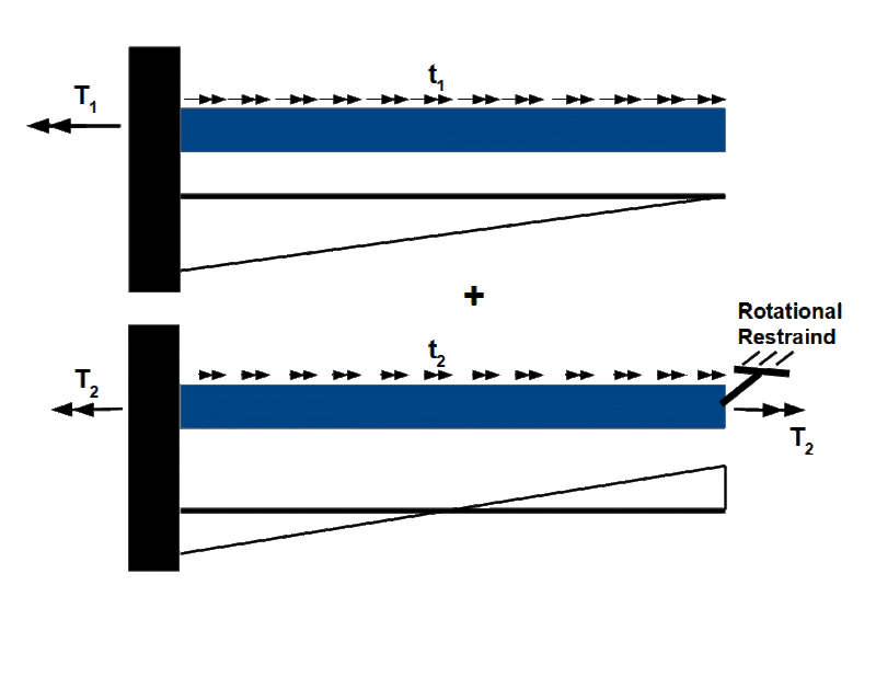
I have a square tube that is fixed on one end (left end on the picture). The square tube is being supported by I beam piles that have bearings on top. So this allows the square tubing to rotate around it's axis.
The square tubing gets a moment loading at the end of the tube. We know what that moment is and we know that it creates a 30 degree deflection at the end of the tube (torsional deflection).
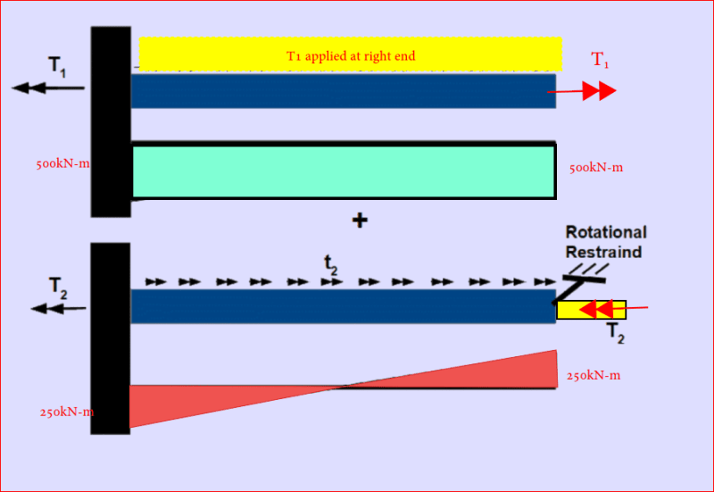
For design purposes and interference with some other parts of design we don't want this tube to rotate that much. We want to allow it to rotate 15 degrees only. So we designed a hard stop at the end. It allows the torque tube to rotate 15 degrees and when the moment gets too high it hits the hard stop that doesn't allow it to rotate more than 15 degrees at the end.
NOW this is the question. How much load does that hard stop takes ?
For the sake of argument let's assume that it takes 1000 KNm to torsionally deflect the tube to 30 degrees at the end of it. At 500 KNm it gets to 15 degrees and hits the hard stop. The torque keeps being applied to 1000 KNm. Does hard stop sees full load divided /2 (half of the full load on left fixed point and half of the load on the new fixed point (the hard stop)) or is load divided 75% for the fixed point to the left and 25% for the new fixed point ton the right (the hard stop) ? My colleague says that new hard stop doesn't see any of the first 500KNm load because the tube is not yet engaged, and once it gets engaged that's when it starts seeing the load, but only other 500KNm are being shared between the fixed points, not total load. Hence 75% to 25% distribution.
Thanks for helping out and sorry if this sounds confusing. I will do my best to explain it better if needed.


