Sorry that I've been out of the thread. I have been busy researching calcs like this. I'm used to doing much larger scale design so going to small scale, fundamental stuff has been a challenging few months. Thank you all for your responses. I will actually keep this information in mind for next time. To provide some further insight....with the ok from my PE I ended up taking the S of a circle and assuming that approximately 1/4 of it is not effective. So I just used 0.75*S. This seemed reasonable since the ineffective weld occurs at what would be the lowest stress portion. This weld is simply the weld of a railing bracket to a solid bar post. So it has a moment which puts the highest stresses on the full weld portion.
KootK: That's a very good idea. Thank you.
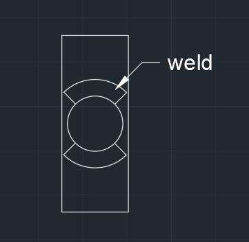
racookpe1978: There will in fact be weld all around. Due to the geometry though, it's unreasonable to assume a full sized fillet all the way around. That is the reason I wanted to determine what the amount of effective weld is. The weld drawn in the sketch is what I assumed it to be. In the sketch the welds are cut off at 45 degree angles, but the actual weld is all around.
BUGGAR: Thanks for that. I didn't know that AutoCAD would do that for me. Yes, I was using the Blodgett method of considering it a circular line. (S=pi*d^2/4)