Eng-Tips is the largest forum for Engineering Professionals on the Internet.

Members share and learn making Eng-Tips Forums the best source of engineering information on the Internet!

  • Congratulations JStephen on being selected by the Eng-Tips community for having the most helpful posts in the forums last week. Way to Go!

Weld assessment for lifting beam 2

sdra2

Mechanical
Joined
Apr 22, 2006
Messages
48
Location
GB
Hi,

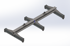
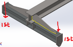
I was wondering if someone could please guide me on how to calculate the stress levels in the welds (the one shown in yellow and its opposite on the other side) for this gusset. Each of the smaller beams is to lift with 15t each end. On the larger beam, two chains from the two upper lugs will meet at 90° for a single point lift. I feel that, in one sense, the weld just adds a little to the section property of the beam but, at the other extreme, would a very small weld not just tear? Thanks.
 

Attachments

  • Lifting beam ET.PNG
    Lifting beam ET.PNG
    117.7 KB · Views: 41
  • Lifting beam ET close-up.PNG
    Lifting beam ET close-up.PNG
    125.8 KB · Views: 44
I agree with you, if the cross beams are properly sized I don't see any use in that weld, it would add very little capacity.
The vertical portion of the weld you can design same as a shear stiffener. The horizontal portion of the weld design for the shear flow assuming it is used for added capacity of the cross beams.
 
That does not look like it provides for stable lifting - be careful.
 

Attachments

Why oh why is that main beam with the two upper lugs not underneath those cross beams? Then you are not relying on any weld or bolts to connect the two.

Unless this lift is very well balanced it will rapidly tilt and create moments on those cross beams which could easily rip them off the main cross beam.

I'm with DVD here - this looks like a recipe for disaster and with such short main lift chains for a total of 60tonne lift, you're in severe danger of failure here IMHO.
 
And the chain lug detail looks like a great way to start cracks in the top flange.
 
To add to MintJulep's remark, the doubling pad is a bad idea as this takes away the direct load path towards the profile's web.
I've seen sections cut out of the web (and a corresponding hole made in the top flange), and have the lifting eye fit in all the way to the bottom.
Not that's something I would propose for a fairly moderate weight lifting rig. All in all the design's off. Looks like it's been thrown together without a lof of thought.
Cut and fit the cross members so that the top and bottom flanges are in the same plane as the main beam's. Rethink the lifting eyes. Don't put the vertical stiffeners in the cross members under the main beam's bottom flange extremities but under the web.
 
" it's been thrown together without a lot of thought "

Better understanding of some fairly basic machine design and welding concepts might help too.
 

Part and Inventory Search

Sponsor

Back
Top