Continue to Site

Eng-Tips is the largest engineering community on the Internet

Intelligent Work Forums for Engineering Professionals

  • Congratulations waross on being selected by the Eng-Tips community for having the most helpful posts in the forums last week. Way to Go!

Voelcker article written in 2002 3

Status
Not open for further replies.

aniiben

Mechanical
May 9, 2017
165
I have a dilemma: why 3b-1 is the correct interpretation?


image_eztfkm.png


image_iwgzgl.png
 
Replies continue below

Recommended for you

pmarc said:
Also, keep in mind that the requirement for the datum feature simulators to be basically located relative to each other does not apply to cases where secondary or tertiary planar datum feature referenced at RMB has a locational relationship to the higher order datums.

pmarc,
Would you mind to comment a little bit more on this statement. Not because is incorrect, but because I DO need more details.

I found a similar statement on MultiMetrics site: "The 2009 Standard now makes material Boundary modifiers applicable to planar surfaces, but only those which are "location constrained", in other words, to those for which maximum material or least material boundaries can be defined.

Is it the same line of thinking?

Basically my question is: if secondary and tertiary are referenced at MMB and they do not have a location relationship to the higher order datums, that is not a valid application?
So, I am questioning your statement above but "adjusted" with MMB instead of RMB, is it still valid?


See page 66 in the attachment for Bill Tandler presentation.

Thank you for coming here and educate your audience. Learning new things everyday.


 https://files.engineering.com/getfile.aspx?folder=bc534817-fc44-4e85-a939-2058c3dd0742&file=GD&T_2009_review.pdf
greenimi,
Yes, this is the same line of thinking.

I would answer your questions like this:
If a secondary or tertiary planar datum feature is referenced at MMB and it has no location relationship to the higher order datums, then this is invalid callout.
If a secondary or tertiary planar datum feature is referenced at MMB and it has a location relationship to the higher order datum(s), then this is valid callout and in simple cases (like the one shown in Tandler's presentation on page 77) the distance between that simulator and the higher order datum is fixed and is equal to the sum of the basic dimension and the half of the profile tolerance value applied to that datum feature.
 
4-31 (b) is even more of a problem as half the profile tolerance zone lies on the far side of the fixed datum feature simulator.

That would be true if the profile tolerance referenced [box]A[/box][box]B [BSC][/box]. It only references [box]A[/box] though, so there is no requirement for the datum feature simulator to be at the middle of the profile tolerance zone.


pylfrm
 
pylfrm = the holes are requiring [A|B[BSC]] which puts the simulator in the middle of the zone. If the perpendicular distance is 5.1 from the A datum feature axis to datum feature B and the datum B simulator is 5 from the datum feature axis there will be an interference problem. It's another diagram that doesn't show the downside and just expects users to trip on their face, like 4-16(b) does. It would have been an excellent place to use the unintuitive (U) modifier to limit the surface to a distance of 5, which would match the crude sketch. It's to wonder what the goal was when Fig 4-30 already clarified the other two options.
 
3DDave said:
If the perpendicular distance is 5.1 from the A datum feature axis to datum feature B and the datum B simulator is 5 from the datum feature axis there will be an interference problem.
Would it? Suppose the holes are not yet there; the part would first be encircled by datum simulator A, and then rotated clockwise until it hits that stop block. The stop block is indeed 15 mm from datum A, but wouldn't the part simply stop its rotation sooner?
Then, with the part held in A|B[BSC], then hole might still be within the position tolerance. (I'm just thinking out loud -- I suspect it might also have to do with the vertical cut, which is conveniently not toleranced in that figure.)
 
belanger - exactly - and the result is not as depicted, but with a single point of contact very close to the axis that 5.1 surface could be at a 5, 10 , 30 degrees inclination to the datum simulator.

So many examples are given that show only the most optimistic outcome, which is not what dimensioning and tolerancing is needed for. It's needed to specify the worst fabricated item the user will pay for. They don't even include a note that this ability absolutely depends on there being a translation disguised as a rotation, which is why it isn't part of Fig 4-30, where the other two versions were already described.
 
3DDave,

Assume the diameter of datum feature D is 40, and the other flat surface is perpendicular to datum feature B and 7.5 from datum axis A. Datum feature B could be about 5.2278 from datum axis A and still barely meet the profile tolerance, with a deviation of +0.1 at the inside end and -0.1 at the outside end. Bringing this surface into contact with the secondary datum feature simulator would result in an inclination of about 1.72°, and the entire profile tolerance zone would be on one side of the datum feature simulator. Do you agree?

If so, I don't understand what you find problematic about this. To me, it seems a lot better than the scenarios based on "maximum contact" which is never defined.


pylfrm
 
pylfrm, At this pace it will be a couple of years before I reverse engineer all the diagrams and provide actual mathematical derivations that are correctly scaled. Perhaps it should be a hobby? Will it cause the committee to fix Fig 4-16(b)?

Anyway - here's the Goegebra version to play with: Link

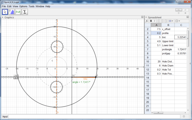
I left the numbers per the diagram and the estimate, which was close to the same offset and does produce the same angle.

What's interesting is the size of the gap at the outer end of the datum feature; much larger than the feature tolerance, labeled profgap:
figure_4_31_b_a9d4yw.png

The number to the right of bsc is the offset of the axis normal to the datum feature B surface.

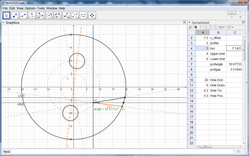
To better see the contributors, a change of values to be more in scale with the diagram's depiction of the variation:
figure_4_31_b_construction_n6ebjf.png

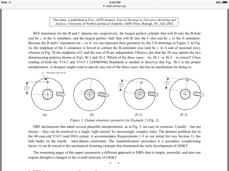
I meant that half the non-rotated zone would be unavailable, not that the part could not be rotated to accommodate it. Essentially, if the part was made in a single operation, such a die cutting, it would require an unusual interpretation, the one you made, to increase the MMB of datum feature B by especially making it non-orthogonal to the nominal location of the holes. If this was investigated before the diagram made it to the standard it should have been in an "or means this" diagram.

I bet that 99% of takers of any test will not understand that the width of datum feature B will affect that 5.2278/whatever value if it was one of the multiple choice answers. The misrepresentation through optimistic simplification is what I am complaining about.

Pushing the offset to -4, the other side of the vertical, nets this:
figure_4_31_b_overcenter_hls5ny.png


ASME should consider creating an interactive version and put it out there for $2500 a copy, heavily DRM'd.

 
Thank you pmarc,

I would have one last question (hopefully) about the “location constrained” subject I pushed for my own clarification: just confirm if I am correct in the following assessment and statements:
In fig 7-59 / Y14.5-2009 page 153, one could never modify datum feature B in the position callout (of the 8mm hole) to use MMB or use the translation modifier for secondary B shown in the FCF. That would be an invalid callout.
“B” in this case, shown configuration must be always RMB. Am I correct?

I am thinking this because B does not have any location relationship to the higher order precedence datums (has only orientation relationship).

Thanks again
 
I am curious, can someone point me to somewhere in the standard as to where the "location constrained" concept is explained/defined? Or is this just a logical conclusion based on the concepts and implication in the standard? If the latter - could someone maybe flesh it out a little and help me understand the basis of the concept a little more? Ie: what make a planar datum feature referenced at MMB valid or not, I am thinking it is more nuanced than just having a defined location/position relationship to higher order datum features - but maybe I'm overthinking it.

Side note - thank you greenimi for posting that resource, I've always been a bit wary of the application of boundary modifiers to planar features, its good to see it laid out and explained with some more clarity.
 
greenimi,
Yes, you are right. The MMB or translation modifier for B would be invalid callout. Or one could say, use of those nodifiers would be meaningless to the definition in this case.

chez311,
The location related concept is logical consequence of the rules. MMB applied to planar datum feature references makes no sense if that planar datum feature doesn't have a location relationship to a higher order datum. So there is no need to overthink it.
 
3DDave,
I may be misreading your diagrams, but if I take just the last one, why is the line MJ passing through the horizontal -5?
 
pmarc said:
3DDave,
I may be misreading your diagrams, but if I take just the last one, why is the line MJ passing through the horizontal -5?
Nevermind, I see it now. Had to use my PC monitor.
 
Status
Not open for further replies.

Part and Inventory Search

Sponsor