Gradually varied flow is an interesting beast.
And that beast does not follow the Manning's equation, except at the midpoint in an infinitely long pipe. The Manning's equation is very useful, but it does not describe reality in an exact way.
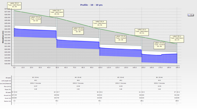
The profiles don't look unusual to me. If you'd like more insight to what's going on, compute the critical depth line and normal depth line for each run of pipe, and draw those onto the graph with a pen. Then google around and learn about M1, M2, M3, S1, S2, and S3 profiles, and transitions. If you have an actual open channel flow hydraulics textbook, that's much better than google. If you're really adventurous, write an excel spreadsheet to do the Direct Step Method and play around with it on your own. That's 4th year engineering hydraulics, or masters level hydraulics, depending on your university program.
Generally, if you want lower velocities, go with flatter slopes, rougher pipes, or bigger pipes. If you're borderline on a regulatory criteria, and you're trying to get something past a reviewer, then it comes down to the reviewer's personality. You could try explaining that the velocity actually varies all along the pipe in a gradually varied flow scenario, and then teach them the science, and then see what they say. I'm not sure what velocity stormcad is reporting. It could be the average along the pipe, or the maximum, or the velocity at the entrance, or at the exit. If you explain those details to the reviewer, then the reviewer might let you just use the Manning's result since that was probably the standard when the regulation was written.
StormCad is a useful and powerful tool, that has probably taken two or three steps past the body of regulations it's intending to serve. Pipe design for storm networks doesn't actually need this amount of complication. DOT culverts and such probably do, depending on the application.
Hydrology, Drainage Analysis, Flood Studies, and Complex Stormwater Litigation for Atlanta and the South East -