Continue to Site

Eng-Tips is the largest engineering community on the Internet

Intelligent Work Forums for Engineering Professionals

  • Congratulations cowski on being selected by the Eng-Tips community for having the most helpful posts in the forums last week. Way to Go!

VC and RC

Status
Not open for further replies.

aniiben

Mechanical
May 9, 2017
165
One more question from the Tolerance Stackup book.


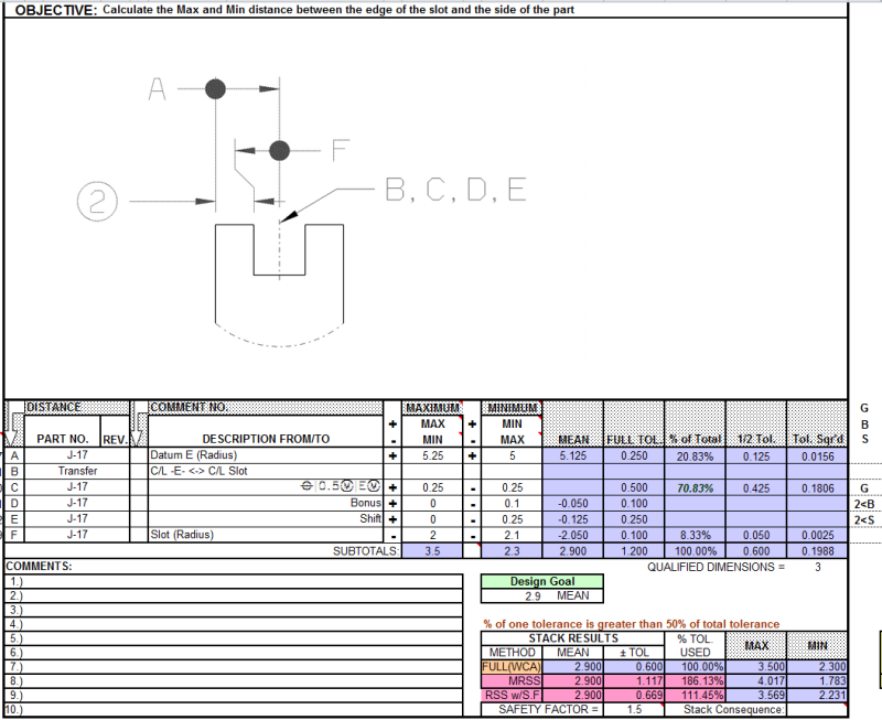
Calculate X max and min distance between the edge of the groove and the side of the part.
For the slot I used VC: 3.5 and RC: 4.9.
X max: (10.5-3.5)/2 = 3.5 -- agreement with the book
x min: (10-4.9)/2 = 2.55-book says: 2.3

The book does NOT use VC and RC calculatons, but I guess if the calculations are done correctly they should match.
What am I missing?

If I subtract the form error of the datum feature E (0.5) from the LMC (10.00) and then use RC boundary (10-0.5 = 9.5; (9.5-4.9)/2= 2.3
The question is why should I subtract the form error of "E" when I use VC and RC method and the book does not have to do it when the answer is given? (the book is using 5 (10/2) in the answer.

Part width: 10.00-10.50-datum feature E
Slot width: 4.0-4.2 , pos 0.5 (MMC) with E (MMC)


 http://files.engineering.com/getfile.aspx?folder=d104285b-d43e-454e-aa1e-c998eb4fddb8&file=Capture.JPG
Replies continue below

Recommended for you

I know, for sure, that a couple of months ago (okay, maybe years rather than months) was a thread here on eng-tips.com where the OP showed a cylinder with a hole thru and we were asked to calculate the minimum distance between the OD and ID. If I remember correctly the OD was the datum feature and the ID was located (position at MMC and position at LMC) relative to the OD (I think 2 cases were shown).
The conclusion was something like the form error of the datum feature must be considered in order to get the calculation correctly.

If I am not mistaken pmarc showed us the correct calculation.

And BTW is bothering me that I cannot find that thread now. I will keep looking, but in the meantime if someone knows what I am talking about, please post it.

 
Not sure that's the one. Was a straight cylindrical pin. And the color on the paper, if I remember correctly was green. I swear I see it in front on my eyes, but I still cannot find it among the threads.
 
datum E is the center plane of the 10.0-10.5 thickness?
 
Re:"datum E is the center plane of the 10.0-10.5 thickness? "

Yes. Datum feature E is the thickness of the plate 10.0 - 10.5.
 
In order for me to understand the analogy with the shown cylindrical pin example, I do have a quick question for everyone in general and for pmarc in particular if he does not mind.

Does the minimum distance (4.7 calculated minimum distance) change if the OD, datum feature A, is referenced at MMC in the positional callout?
What about if it is at LMC in the same ID position callout?

In other words, position of the ID will have some available datum shift.
 
Hmmmm. I don't know if min will change in pmarc's scenarios / cases. 4.7 is the number I got.
Am I correct?
 
Initially I did not see that was a two part question (MMC/MMB and LMC/LMB for the datum feature A).
So, to re-answer:
4.7 (“X” minimum distance in pmarc’s case) if datum feature A is callout at MMB in the positional callout of the ID
and 4.8 if datum feature A is callout at LMB in the positional callout of the ID.

Pmarc,
Am I correct? Or I confuse the audience even more?
We are talking about a side-subject related with the original thread:
Your thread is here: (for a quick reference)


THEN, going back to the OP original question
If “Kurlikovski” method is used, then no need to subtract the form error on datum feature E: 10.5-10.0 = 0.5), as you will get it in the datum shift (B at MMB)
If VC/ RC method is used then you do need to take care of the form error and the non-requirement of the perfect form at LMC when x min is calculated.

Enough said. I am waiting for the experts to chime in. Not sure I got this issue solved. I just hope.
 
greenimi,

Allow me to answer your question (hopefully) by answering aniiben's question:
aniiben said:
Does the minimum distance (4.7 calculated minimum distance) change if the OD, datum feature A, is referenced at MMC in the positional callout?
What about if it is at LMC in the same ID position callout?

1. If the OD, datum feature A, is referenced at MMB, the minimum distance is 4.7.

2. If the OD, datum feature A, is referenced at LMB, the minimum distance is also 4.7.
"Why is that?", you may ask. It is because the size of LMB boundary of datum feature A is not 19.9, but 19.7.
 
I have to wrap my head around this 4.7 minimum wall when datum feature A (OD) is at LMB in the positional callout of the OD.
Not sure I understand it at this point.
Are you saying that the perfect form at LMC is not required when the OD is at least material condition? Not sure where “It is because the size of LMB boundary of datum feature A is not 19.9, but 19.7” is coming from. Specially 19.7.

Let me recap a bit: (following your described cases)
OD: Datum feature A: Ø19.9 - 20.1
ID: Ø9.9 – 10.1,
Case 1: position Ø 0.2 LMC wrt A at LMB
Case 2: position Ø 0 MMC wrt A at LMB
Both of these cases will drive a minimum possible distance x min (between the OD and ID) of 4.7?

I get 4.8 no matter how I spin it.
Any help, maybe even “for a six years old child instructions” will be greatly appreciated.

I just want to say, it is a simple cylindrical part with a hole in it………”closed mind of the month” award is mine.
I think I need a vacation…..
 
Excercise2_vx0iwy.png

For the 2B and 2S condition, the < indicates the column the MMC condition occurs, in this case, line F for the bonus shown on line D, and line A for the shift on line E.
 
Status
Not open for further replies.

Part and Inventory Search

Sponsor