Continue to Site

Eng-Tips is the largest engineering community on the Internet

Intelligent Work Forums for Engineering Professionals

  • Congratulations cowski on being selected by the Eng-Tips community for having the most helpful posts in the forums last week. Way to Go!

Use of Steel SMF in Wood Frame Building 5

Status
Not open for further replies.

smwa

Structural
Aug 10, 2006
21
I'm curious about how to brace the hinge points in a Reduced Beam Flange Special Moment Frame with a wood diaphragm. I've seen a lot of steel angle braces back to the wood diaphragm, but it doesn't seem like the wood diaphragm will be able to resist the code required brace load (6% of beam flange strength). This is especially a concern when the MF is installed at the front of the building, where there is diaphragm at one side only. What are some other details designers have used that can be shown to work for the code required brace load?

In most of our residential wood frame projects, the MF design is controlled by drift, and the actual member stress is very low, with D/C ratio of 0.25 to 0.4. This implies that if I apply the Omega level load, the MF will still remain elastic, and the hinge will not develop. If so, is there a rationale for reducing the brace load at the hinge locations, or simply not brace the hinge points, since the hinge will not form under Omega level load?

The above also lead to the question that if a SMF remains elastic, is it essentially behaving like an OMF with the built-in safety mechanisms? The drift calculation for SMF (Cd/R=0.688)is significantly lower than OMF (Cd/R=0.857). Is the SMF drift calculation accurate, if it is behaving like an OMF?

Thanks in advance,

Stan
 
Replies continue below

Recommended for you

smwa said:
However, I know before Omega load was introduced, people used to use R=1 to check for elements that needs to remain elastic. My guess is that the code committee determined that R=1 is too conservative, and very unlikely for a structural element to experience that load level.

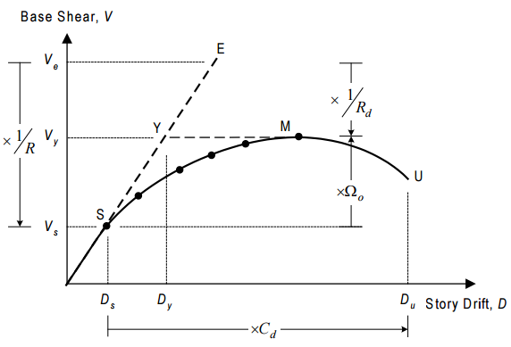
I can shed a little more light on this. At least... I think I can. In Canada, and many other countries, we have two R factors:

1) Ro (over-strength, 1/Omega) which accounts for the base shear differential between the point of first significant yield and the point where the entire structural lateral system is thought to have given way.

2) Rd (ductility) which accounts for the base shear differential between the spot that Ro gets you to and the R=1 demand level.

The sketch below does it better justice. In the US, Rd and Ro are combined into a single R factor. Anyhow, the moral of the story is that you only have to amplify by the Ro (Omega) to roughly ensure a member's elastic behavior. R=1 is indeed over conservative. I apologize if I misled you in that regard earlier.

Capture_qtynl7.png


I like to debate structural engineering theory -- a lot. If I challenge you on something, know that I'm doing so because I respect your opinion enough to either change it or adopt it.
 
KootK -

That is my favorite diagram for explaining seismic concepts. It explains why we have R, Cd and Omega all in one simple force deflection curve.

 
KootK, Thanks for the graph. Good to know that's how other codes handle the difference between Omega an R. Is the graph truncated? What is the Base Shear value corresponding to Du?

In ASCE the Cd value is somewhere between Omega & R. Where Cd is closer to R value for more rigid systems such as walls, and Cd is closer to Omega for more flexible systems such as cantilever columns. Kind of make sense to me that in a rigid system, the element is more likely to experience ground acceleration, or R=1. If my logic is correct, the ASCE Cd value assumes that SMF (Cd/R=0.688) is more flexible than OMF (Cd/R=0.857). Which brings back my original concern that if the plastic hinges do not develop in SMF, then should we calculate the drift based on the SMF Cd & R values, especially when the SMF design is drift controlled.
 
Yes, you need to calculate drift based on whatever R value you used because you are reducing the seismic load on the assumption that the energy will be dissipated by the formation of plastic hinges.
 
smwa said:
Good to know that's how other codes handle the difference between Omega an R.

The graph pertains specifically to US codes.

smwa said:
Is the graph truncated?

Nope.

smwa said:
What is the Base Shear value corresponding to Du?

I don't know. I'm not sure that anyone does really unless testing or at least a pushover analysis has been performed.

smwa said:
Which brings back my original concern that if the plastic hinges do not develop in SMF, then should we calculate the drift based on the SMF Cd & R values, especially when the SMF design is drift controlled.

Personally, I think that drift should be calculated based on Cd = R for the reasons discussed above. Of course, that will have undesirable economic impacts in your marketplace.

Another wrinkle is that US R values have a bit of froo-froo fudge built in to pseudo account for anticipated redundancy. You can see this in the dual system numbers.

smwa said:
Where Cd is closer to R value for more rigid systems such as walls, and Cd is closer to Omega for more flexible systems such as cantilever columns. Kind of make sense to me that in a rigid system, the element is more likely to experience ground acceleration, or R=1.

I observe the same trend but interpret it differently. With a flexible system, much of your R will be comprised of Ro (omega) and relatively less will be Rd(ductility). That make sense since a moment/cantilever frame will sustain relatively little damage at peak inelastic displacement. Thus Cd close to omega. With a wall, it's the reverse. Lots of damage at peak inelastic placement and thus a Cd value better correlated with Rd or R.

I like to debate structural engineering theory -- a lot. If I challenge you on something, know that I'm doing so because I respect your opinion enough to either change it or adopt it.
 
Kootk,

Thanks for the chart and explanations. I wish I had see it / read them years ago.
 
You're most welcome Archie. I've always found getting good explanations for seismic code intent to be excruciating. It seems as though one could sum it all up in one good 10 page white paper but, as far as I can tell, no such document exists.

I like to debate structural engineering theory -- a lot. If I challenge you on something, know that I'm doing so because I respect your opinion enough to either change it or adopt it.
 
Status
Not open for further replies.

Part and Inventory Search

Sponsor