Continue to Site

Eng-Tips is the largest engineering community on the Internet

Intelligent Work Forums for Engineering Professionals

  • Congratulations cowski on being selected by the Eng-Tips community for having the most helpful posts in the forums last week. Way to Go!

Use of Steel SMF in Wood Frame Building 5

Status
Not open for further replies.

smwa

Structural
Aug 10, 2006
21
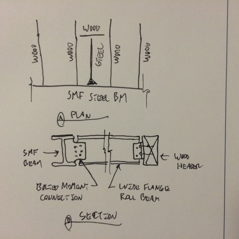
I'm curious about how to brace the hinge points in a Reduced Beam Flange Special Moment Frame with a wood diaphragm. I've seen a lot of steel angle braces back to the wood diaphragm, but it doesn't seem like the wood diaphragm will be able to resist the code required brace load (6% of beam flange strength). This is especially a concern when the MF is installed at the front of the building, where there is diaphragm at one side only. What are some other details designers have used that can be shown to work for the code required brace load?

In most of our residential wood frame projects, the MF design is controlled by drift, and the actual member stress is very low, with D/C ratio of 0.25 to 0.4. This implies that if I apply the Omega level load, the MF will still remain elastic, and the hinge will not develop. If so, is there a rationale for reducing the brace load at the hinge locations, or simply not brace the hinge points, since the hinge will not form under Omega level load?

The above also lead to the question that if a SMF remains elastic, is it essentially behaving like an OMF with the built-in safety mechanisms? The drift calculation for SMF (Cd/R=0.688)is significantly lower than OMF (Cd/R=0.857). Is the SMF drift calculation accurate, if it is behaving like an OMF?

Thanks in advance,

Stan
 
Replies continue below

Recommended for you

1) I think that you've got to assume plastic beam hinging if you're going to use SMF force deduction values. Otherwise, go with IMF/OMF if code allows based on your SDC etc.

2) A detail that I would support would be a torsional bracing scheme using a short steel section with a bolted moment connection to the SMF beam and headered off to the primary wood framing tying in. This only works where your wood framing is perpendicular to your SMS beam.

I like to debate structural engineering theory -- a lot. If I challenge you on something, know that I'm doing so because I respect your opinion enough to either change it or adopt it.
 
image_lewof9.jpg


I like to debate structural engineering theory -- a lot. If I challenge you on something, know that I'm doing so because I respect your opinion enough to either change it or adopt it.
 
The strength requirement you can meet fairly easily. Generally with with just full height blocking or joists attached to stiffener plates that are welded on three sides.

Good luck meeting the stiffness requirement though. If someone knows how to meet the stiffness requirement (including effects of diaphragm deflection between other lateral elements) Id be interested to hear because I think it's nearly impossible with plywood diaphragm unless you have an unusually tight spacing of lateral elements in the perpendicular direction. A lot of engineers I know just outright ignore it. I don't follow that logic, I pretty much just use ordinary frames in wood frame buildings. Even in SDC D & E they are allowed with some exceptions.

If you really need a special frame I would consider using a premanifactured one such as Simpson Moment Frame or Hardy Moment Frame. Neither of these frames have bracing requirements along the beam span.
 
Agreed. You will have a very hard time with the stiffness requirement of the braces. Wood does not play well with steel, especially in high seismic. In lieu of the SMF you may want to look at the Simpson portal frames instead.
 
This is one of the reasons that the Simpson frames were developed. The Simpson frames don't require lateral bracing. Simpson SMF
 
Hi jdgenginee, mike20793 & gumpmaster,

We've been getting a lot of push back from GC's about using Simpson SMF. The reasons being:
1. Simpson only allow 1/8" tolerance. This is a very tight tolerance for an existing building that is neither plumb nor level. Most GC's don't want to be responsible for a wrong measurement and end up paying for the frame themselves.
2. The GC's will not order the Simpson frames until the foundation is poured, and the anchor bolts are set. At that point it is a 6 week lead time. Most steel fabricators can fabricate SMF's quicker, and allow you to make adjustments in the shop drawing review process.
3. The GC's steel subcontractor will not install the Simpson frames, because they feel like they are losing business to Simpson. Residential GC's are not set up to be erecting steel themselves.
4. Cost. Most GC's tell me they can get RBS SMF's fabricated for less.

KootK,

Thanks for the detail. It makes sense. However, most of our SMF's in the Bay Area are parallel to the floor joists.

Anyone with any thoughts about the second half of my original post? I'm struggling to understand if I need to follow such onerous RBS bracing requirement by code, when the RBS in my case will remain elastic even under Omega level loading. I understand that the RBS will develop a hinge if R=1.0 (ground acceleration), but isn't the Omega load suppose to represent the maximum possible load the element will experience?
 
I also work in the bay area and have seen and used Simpson frames on several projects. (A lot of SF soft story projects are designed with them) I believe if you are utilizing the R = 8 of a special moment frame you need to meet all detailing requirements including beam bracing. I do not believe designing the frame for the omega level force relieves you of this requirement.

As mentioned previously it is my strong opinion you can not feasiby brace a SMF in a wood building. Therefore, if you are going with a conventional moment frame i would recommend cacling / detailing as ordinary.
 
1. Yes you definitely have to brace the RBS. It's called a reduced beam section for a reason. You are intentionally reducing the cross section to encourage a hinge to form there. Not bracing it is a direct violation of the code. Designing a RBS to remain elastic is a terrible waste of money and shows someone doesn't understand the concept of seismic structural design.

2. There's no way the Simpson frames are more expensive than all the crazy detailing associated with SMF, plus designing for overstrength. You and your contractors are poorly informed. I can buy the tolerance thing but you have terrible GC's if that's the kinda stuff they're telling you.

3. No that's not what the overstrength factor is used for at all. It's to ensure certain parts of the building remain elastic during a seismic event so plastic hinges form where you expect them to (at reduced beam sections).
 
I cant buy the tolerance argument, its not like you have some greater tolerance when welding up a SMF. If they mess up the dimensions with the SMF they steel need to order new beams or columns. I had a new mid-rise wood building with some SMF frames, the steel guy was not used to working with wood and had to much gap for the beam to column welds. Talked and talked about how it was ok that the buttered up the joint. They did not like replacing the beams and needing to remove the surrounding framing.

If you want to use the pre-qualified connection shown in AISC 358 you need to follow all requirements or get your connection tested without bracing like Simpson. See AISC 341-10 section E3.4b.

As a general note I always provide bracing at the plastic hinge even when the code allows for removal of bracing as the moment frame system behave better.
 
Thanks for all of your input. I think I need to clarify my question a little. I know bracing at the plastic hinge is required by code, and I know I need to provide that for SMF. I'm questioning is if a plastic hinge will really form in certain cases. Just because we call it a plastic hinge, it doesn't mean that it will form. In my case, the SMF in residential projects have very little gravity load, so it is totally controlled by drift requirement. The stress in the members are very low. If I check the Reduced Beam Section with Overstrength load, and it still remain elastic, then will the plastic hinge really form?
 
My relatively simple thoughts on this subject:
1) Overstrength loads are not viewed as the maximum load the connection can see. That used to be the case some years ago (1994 UBC-ish), but not anymore. At least not for SMF moment connections.

2) You've got options, OMF, R= 3 and such for certain seismic design categories.

3) Local buckling of the beam in the vicinity of the RBS is a real phenomena. And, it definitely reduces the ductility of the frame. You can't call yourself an SMF or expect an R value akin to an SMF without following that provision.

4) If you left out that bracing would your structure be "okay" under a seismic load? Maybe. Or, maybe you'd get some localized failure at the RBS that reduces the ductility. Maybe that impacts your structure as a whole. If you were dragged into court, then you would be responsible for not following the code provisions.

5) There are other outs allowed by code. But, they're expensive. You can go through 358 testing protocols for the type of configuration you want to use.

 
Agree with JoshPlum. The general intent of seismic design in high seismic areas is a capacity based approach. The implementation isn't perfect, but you are trying to create "fuses". In the braced frame the fuse is the brace and the gussets. In a moment frame the fuse is the RBS. In high seismic areas the code typically wants you to design for a ductile mechanism so in the event the building sees seismic forces that are higher than anticipated you still have a ductile failure. Therefore, if you are using an R=8 even if your analysis with an overstrength factor says the beam does not yield you need to follow the detailing requirements as there could be a seismic event higher than anticipated. If you aren't going to follow the detailing requirements you need to reclassify your system so one with a lower R value (as long as it is still allowed in the SDC).
 
The stresses per a code check are irrelevant though - the frame is detailed to allow for inelastic action to dissipate the energy of the earthquake. Its the forming of the plastic hinge that allows for the R=8 and reduced 'apparent' seismic load.
 
OP said:
If I check the Reduced Beam Section with Overstrength load, and it still remain elastic, then will the plastic hinge really form?

When elements in an RBS SMF building are designed to over strength, they are kept elastic by ensuring that they don't yield before the RBS's go completely plastic. The "overstrength" is the over strength of the SMF system. So, to check the RBS for over strength loading is to essentially say "I'm going to make sure that this beam remains elastic until well after it goes completely plastic!". Hopefully you see the incongruency inherent in that statement.

The only way to claim that the RBS's remain elastic is to design them for R=1.0. And even that's dubious.

I like to debate structural engineering theory -- a lot. If I challenge you on something, know that I'm doing so because I respect your opinion enough to either change it or adopt it.
 
As I said get your connection tested to show the limitations you have placed on the frame ensure that you will not need bracing. This is why you cant use Simpson SMF for any beam configuration.

There seems to be this continuing misconception about the overstrength factor. The overstrength factor is best described as the being the building relative overstrength. Placing overstrength onto any component does not ensure that it will remains elastic, it is elevating the loads to force your fuse to fail first and dissipate energy. Members that use overstrength could still experience inelastic behavior, they should not fail before the primary lateral elements dissipate lateral energy.
 
Thanks for all the replies. I agree that the only way to know that the RBS remains elastic is to check it for R=1. However, somewhere between Omega load and R=1 loading, there is no guarantee that the plastic hinge will form either. The energy dissipation mechanism within the SMF design may not occur. If my SMF member sizes is controlled by drift, I can design for drift using Cd/R = 5.5/8.0 = 0.688. But if I design it as a OMF, the Cd/R = 3.0/3.5 = 0.857, which results in larger drift. It's a significant difference, even though there is a good change the both frames will remain in the elastic range. My 3-story building is too tall to use OMF, so I will need to use SMF, but want to make sure the drift calculation is correct even if there is a good change the plastic hinges will not form.

 
sandman21 said:
There seems to be this continuing misconception about the overstrength factor... Placing overstrength onto any component does not ensure that it will remains elastic...Members that use overstrength could still experience inelastic behavior

If it's a misconception, it's a misconception perpetuated by ASCE7. While the ASCE7 over strength provisions may not do a perfect job of keeping certain members elastic, that is ASCE7's intent. I see the Omega business as essentially a weaker, and often more convenient, form of true capacity design.

Capture_rp7rlr.png


I like to debate structural engineering theory -- a lot. If I challenge you on something, know that I'm doing so because I respect your opinion enough to either change it or adopt it.
 
@smwa: I take your point regarding the drift estimate confusion. I really don't know how ASCE arrived at their Cd values. In Canada, NZ, Mexico, and Europe, Cd = R for most building periods and this becomes a moot point. That, per equal displacement theory and Nathan Newark's recommendations.

I like to debate structural engineering theory -- a lot. If I challenge you on something, know that I'm doing so because I respect your opinion enough to either change it or adopt it.
 
Thanks for your input KootK.

C12.4.3 description is the basis of my understanding of the Omega load. However, I know before Omega load was introduced, people used to use R=1 to check for elements that needs to remain elastic. My guess is that the code committee determined that R=1 is too conservative, and very unlikely for a structural element to experience that load level.

That's interesting that other codes use Cd=R. That makes sense if drift is calculated using ASD load. Seems like Cd should = 0.7R if using LRFD load to calculate drift. It'll be interesting to know how ASCE arrives at the Cd values. Maybe they are aiming for Cd = 0.7R with adjustments for different systems.
 
Status
Not open for further replies.

Part and Inventory Search

Sponsor