Navigation
Install the app
How to install the app on iOS
Follow along with the video below to see how to install our site as a web app on your home screen.
Note: This feature may not be available in some browsers.
More options
Style variation
-
Congratulations MintJulep on being selected by the Eng-Tips community for having the most helpful posts in the forums last week. Way to Go!
You are using an out of date browser. It may not display this or other websites correctly.
You should upgrade or use an alternative browser.
You should upgrade or use an alternative browser.
Unilateral composite profile problem
- Thread starter sendithard
- Start date
- Status
- Not open for further replies.
pmarc
Mechanical
- Sep 2, 2008
- 3,248
sendithard,
Have you noticed that the 3 position callouts in my example, when combined with the size requirement, create 3 virtual condition boundaries which are exactly the same as the boundaries created by the composite profile tolerance in your example?
(The fourth boundary - i.e., the inner/MMB boundary for the lower segment profile - is redundant.)
- Thread starter
- #22
sendithard
Industrial
- Thread starter
- #24
sendithard
Industrial
Pmarc,
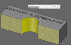
Sorry my last picture has the incorrect engraving on the part....it is 20.05 part diameter not 20.5, but the model is correct(edited pic, now correct). Below is another example. Since the upper segment is analyzing the surface when it is machined at 20.05, some of the tolerance is gone due to size so you lose location tolerance that is important to have. I'm dealing with tighter tolerances than this on the shop floor and realistically the tolerances are becoming so tight you are pushing the limits of any method of measurements uncertainty. 25 microns of lost location deviation can make or break a pass/fail.
So while I understand the point of your example, Your LMC position callout allows for more error in location than this upper segment. This is due to the use of unilateral, if it was bilateral all would be good.
edited img, I had a mistake in it on the max allowable size of the feature in the upper segment.

Last edited:
pmarc
At para 11.6.1.1 in Y14.5-2018 clearly states irregular shaped feature, a round hole in this example is just a regular FOS.

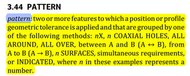
There is an all around symbol used in the example of Figure 11-24, according to the para 3.44, this is a pattern features, a single hole is not a pattern.

I still think a single round hole can not use composite profile callout based on the reasons shown above.
Happy Tnanksgiving to all GD&T forum members
Season
At para 11.6.1.1 in Y14.5-2018 clearly states irregular shaped feature, a round hole in this example is just a regular FOS.

There is an all around symbol used in the example of Figure 11-24, according to the para 3.44, this is a pattern features, a single hole is not a pattern.

I still think a single round hole can not use composite profile callout based on the reasons shown above.
Happy Tnanksgiving to all GD&T forum members
Season
Last edited:
- Thread starter
- #26
sendithard
Industrial
pmarc,
my brain hurts after a full day of getting beat up. After a recalc on your example, I think your example matches the above image diagram. So if you replaced the composite tolerance callout with yours you get similar results but you cannot get bonus on profile so I'm too late in the day to figure it all out. I do know making a part at what it should be made at loses important tolerance in the PLTZF. The upper segment is my problem child.
Season,
There are people in the camp that surface profile should replace many previous type callouts. I'm one of them with many of the dumb ass non feature of size positional callouts I see everyday. I prefer position when the feature is robust, but I can tell you the callouts I see from non-features of size and made up shit is crazy and I am pushing us more and more towards profile. Mating parts don't care about a fake axis, they care about surface contact. We assemble most of our parts so I see the results of using position vs profile and profile wins hands down.
So let's say you want to place a hole in your ceiling for a fan. You provide a print for a single hole that uses ABC within 5 inches ABC profile. Let's assume the installation person understands surface profile. He sees you placed a composite profile segment underneath the 5 inches tolerance at let's say .1inches with no datums.....he knows you are telling him to make sure the hole is located within 5 inches but to make the damn hole within .1 inches of the proper diameter. So this is an example of a single hole composite. Easily replicated with a normal positional callout with a +- hole diameter and huge 5 inch positional callout, but profile can do the same as position. The problem is you can't get bonus with profile.
Last edited:
Burunduk
Mechanical
- May 2, 2019
- 2,580
SeasonLee,
The standard acknowlesges that composite profile can apply to a single feature which is not any kind of a pattern. That's why instead of P(attern)LTZF and FRTZF the description in the relevant section involves "profile-locating tolerance zone" and the "profile
feature tolerance zone" in the context of single features (look them up in your copy of Y14.5).
sendithard,
Another way to look at the problem you are describing is that the upper segment creates a tolerance band between 2 coaxial cylinders, one of Dia 20, the other Dia 20.2, fixed relative to the DRF.
The lower segment creates a band between Dia 20 and Dia 20.1, normal to the primary datum plane and floating, to refine only size, form and orientation. However once it starts to float trying to approve an actual feature, it becomes partially unusable on the opposite side from the float direction, as part of it gets out of the first segment's limits. So yes, you will have a very limited float. But this scheme is still less restrictive than having just the 2nd segment's value relative to A,B,C.
Burunduk
Mechanical
- May 2, 2019
- 2,580
To me it looks like someone tried to convert Position of 0 at MMC with a unilateral +X.XX/0 size tolerance to profile.Some engineers got their hands on Y14.5-2018 then decided to overuse every new fancy call-out.
- Status
- Not open for further replies.
Similar threads
- Replies
- 19
- Views
- 10K
- Replies
- 15
- Views
- 1K
- Locked
- Question
- Replies
- 59
- Views
- 4K
- Locked
- Question
- Replies
- 21
- Views
- 10K
- Replies
- 31
- Views
- 7K


