Continue to Site

Eng-Tips is the largest engineering community on the Internet

Intelligent Work Forums for Engineering Professionals

  • Congratulations waross on being selected by the Eng-Tips community for having the most helpful posts in the forums last week. Way to Go!

Two beams fitted inside each other, spot welded at the ends. What load size can they withstand? 17

Status
Not open for further replies.

nikoD

Mechanical
Oct 5, 2020
6
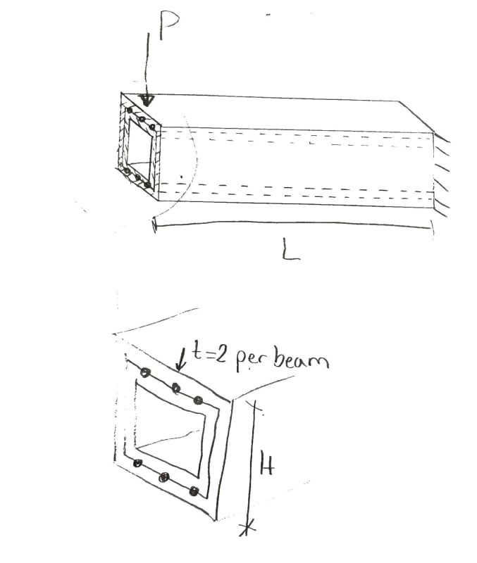
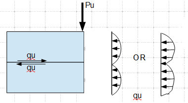
I have a friend who asked me how I would go about analyzing the max value of P in the situation shown in the picture.
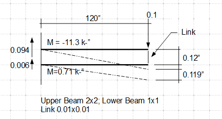
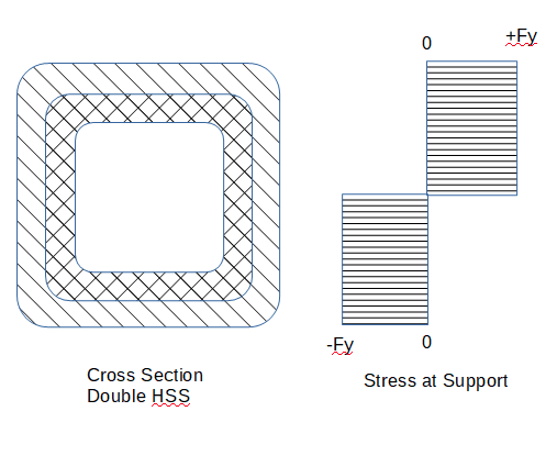
Two steel profiles are fitted into each other. Both are fixed to the support, but the beams are only connected to each other with spot welds at the beams' ends.
2020_10_05_13.48_Office_Lens_t85tkj.jpg

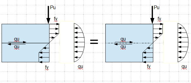
To me it looks as if the stresses from the outer profile must be transferred to the inner profile through the spot welds, which could reduce the load that the profiles can withstand.
[ul]
[li]What theories are of importance to analyzing this situation? (e.g. Grashoff?)[/li]
[li]Will the spot welds be a limiting factor to the size of P?[/li]
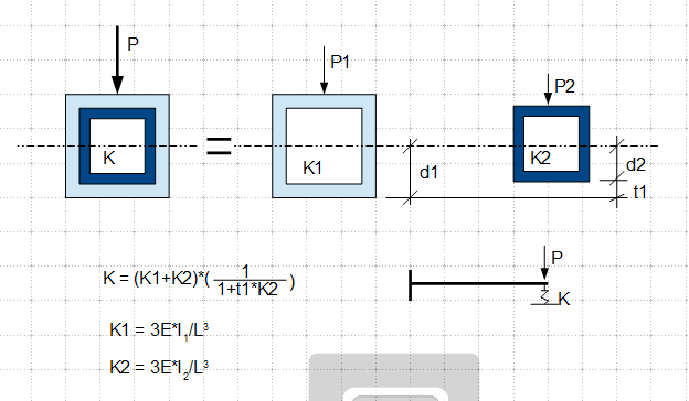
[li]How would you go about analyzing this scenario, if both the displacements and P_yield is of importance?[/li]
[li]How do you calculate the max value of P?[/li]
[/ul]
The scenario left me curious, as I have barely any idea how to answer his question.
 
Replies continue below

Recommended for you

BA,

I got you, and think you are correct/make sense, though I am not into the limit state. My though still remains on elastic range.
 
BA,

Is this what you meant?

image_eajs58.png
 
IMO, it is more likely be either case below. The case on the left indicates condition of no friction between the beams. The case to the right indicates the influence of friction and/or contact stress.

image_fi6qrr.png
 
r13,

This is what I had in mind, pretty standard stuff I believe.

But even if there is a gap between the two HSS shapes, they may not reach full yield at the same time, but with slow increase in applied load, they will both eventually reach yield.

image_cqcn8y.png


BA
 
BA,

The answer to my previous question is "yes" then. Interesting, I wish there is literature addresses this phenomenon.

I guess this concept can extend to slab on beams, the ultimate load capacity will be the same, with or without studs/connections in between. Correct?
 
r13 said:
BA,

The answer to my previous question is "yes" then. Interesting, I wish there is literature addresses this phenomenon.

I don't believe the answer to your previous question is "yes" and I don't believe there is a shortage of literature on Limit States Design.

BA
 
r13 said:
I guess this concept can extend to slab on beams, the ultimate load capacity will be the same, with or without studs/connections in between. Correct?

No, that is not correct. The ultimate load capacity of a composite beam relies on a connection between the steel beam and concrete slab. The composite section, if transformed to steel, is much larger than that of the steel beam by itself.

In the current situation, the plastic modulus of the combined section is precisely the same as the sum of the two separate values. An HSS 20x20x4 has the same Z value as HSS 20x20x2 plus HSS 16x16x2.

It is not a contradiction. In the case of the composite beam with no connection to the slab, you could argue that the composite load capacity is equal to the sum of the beam and slab, considered separately. That would not help very much though, as it would be very little more than the capacity of the steel beam by itself.

BA
 
r13 said:
If the above statement stands, the end, or any, plane should be remain plane, and stress distribution would follow Hook's Law.

They do (within the approximations inherent in beam theory), as shown in the analysis results.

Doug Jenkins
Interactive Design Services
 
BA said:
I don't believe the answer to your previous question is "yes"

So what is the difference between the cases - stress on two members stacked together and a integral member with rigidity equal the sum of the two members, if both has the same ultimate strength? There must be something I've missed. If you don't mind, can you provide a reference to the first case. Thanks.
 
BA said:
The maximum load P carried by the double member is unaffected by the strength of weld at the end of the members; similarly, it is unaffected by a small gap between members. The smaller member could be terminated half way between P and the support without affecting the value of Pmax.

Agreed, assuming you mean that both members are fixed at the support, and the inner one terminates half way along the length (which I'm sure you did :)).

What happens under elastic conditions is an interesting question though.

For instance, under the scenario above the inner member has the same curvature as the outer one all along its length, and hence the same M/EI, so it must have a point moment magically transmitted to it at its "free" end, without any means of transmitting a horizontal force.

Doug Jenkins
Interactive Design Services
 
r13 - Your diagram (posted 19:40) shows one beam sitting on top of another one.

That is a different situation as far as strain at the interface is concerned, but the combined moment capacity is the same, and the elastic response would be the same (so long as both beams remained fully elastic), for a point load at the end.

For a distributed load the elastic response would be different because in one case the members have to remain in contact along their length, and in the other case they don't.


Doug Jenkins
Interactive Design Services
 
IDS (black) said:
BA (red)[/color]]Agreed, assuming you mean that both members are fixed at the support, and the inner one terminates half way along the length (which I'm sure you did :)). I did!

What happens under elastic conditions is an interesting question though. I haven't really thought about it, but I'll take your word for it, Doug.

For instance, under the scenario above the inner member has the same curvature as the outer one all along its length, and hence the same M/EI, so it must have a point moment magically transmitted to it at its "free" end, without any means of transmitting a horizontal force. It seems to me that the two members share the point load through direct bearing, assuming no gaps between them, so I see no need for a moment applied at the free end or a need for a horizontal force.

If there is a gap between the two HSS shapes, it depends on where the gap is. The inside member has to be welded first at the support, then the outer member placed around it. It would be simplest to let the outer member rest on the inner one while the welding is done. That would mean no gap on top, double gap on bottom. In that case, I believe the two HSS members would share the point load in accordance with their stiffness and everything would be the same as the case of no gap. Both members would reach their respective Mp simultaneously.

If there is a gap between the HSS shapes, the outer one would have to be supported by a shim at each end. In that case, point load P would be shared in accordance with stiffness as before, some of the point load passing through the shim at the free end.

If the upper gap could somehow magically be maintained without a shim, The outer HSS would have to deflect until it came in contact with the inner HSS. That could complicate elastic calculations a bit, but in the end, both shapes would arrive at Mp, not simultaneously, but the ultimate value of P would be the same as before.

BA
 
BA - with the half length inner member scenario, at the point of first contact the outer tube has a moment of PL/2 and the inner tube has no moment.

But (assuming perfect contact and zero friction) the curvature of the two tubes must be the same, so the inner tube must have a moment in proportion to its EI value.

In the real structure, where there is some finite gap, the initial contact of the top surfaces will rotate the inner tube until it comes into contact at the bottom surface, and that contact will generate a moment until the curvature of the inner tube matches the curvature of the outer tube.

So there is a "point" moment transmitted (in reality over some finite length), without any horizontal force transfer between the tubes.

Doug Jenkins
Interactive Design Services
 
IDS,

Yes, my diagram was showing stacked beam, similar, though not exact, to the upper flange of the tubes. You are correct in saying the total reaction of the system for the two cases are the same, but one would be stressed much more than the other, quite different if the tubes were made composite. Below is a 2D analysis, just to show how the member behave under such condition. I think analysis by solid element should provide better insight, do you think so? Note I am not familiar with solid element though.

image_e7f84d.png
 
r13 - stacked beams are not the same as concentric tubes (as has been said numerous times in this thread).

With stacked beams the composite member is deeper than either of the member that make it up.

With concentric tubes the composite member is the same depth as the outer member.

I posted results of my analysis yesterday.


Doug Jenkins
Interactive Design Services
 
IDS,

Does not mean not believe in your analytical, given the opportunity (a software) available, I would like to see myself. Does the end forces in proportion, and conform to composite beam?
 
As the analysis on effects of contact force and shear friction between fitted tubes are beyond my capability at this time, I am ceasing may case with a citation (abstract of the research paper titled "Tensile and bending properties of double-walled carbon nanotubes", August 2004 Journal of Physics D Applied Physics) for the interested parties.

"Atomistic simulations are performed to investigate the mechanical properties of uniaxial tensile and bending behaviours of double-walled carbon nanotubes. The second-generation reactive empirical bond-order potential and four different van der Waals (vdW) potentials are used to describe bonding and non-bonding atomic interactions, respectively. It is found that the tensile and bending behaviours are insensitive to the choice of vdW potential. It is shown that the effect of the helicity of nanotubes on the elastic modulus and the tensile strength is significant, while the effect of the nanotube diameter is moderate. Our simulations show that the outer tube always reaches its tensile strength first, suggesting the 'sword-in-sheath' failure mechanism. For the bending deformation, a strong non-linearity between the deformation and load is observed at small deformations, while a nearly linear relation is observed at large deformations."
 
r13 - that paper looks quite interesting, but it's way over-complicating things. The only equation you need is:
deflection = FL^3/3EI.

Consider three equal length cantilevers, all fixed at the same elevation.
One is a square tube of outside dimensions D and wall thickness t.
Two is also of outside dimension D and wall thickness t/2.
Three is of outside dimension D-t and wall thickness t/2

Calculate the second moment of area for each tube I1, I2, I3, and note that I1 = I2+I3.
Calculate end deflections for a unit weight.
Distribute a force F between the three tubes so that they have exactly equal deflection, i.e. F.I2/2I1 to 2, FI3/2I1 to 3, and F/2 to 1
The CLs of the three tubes now follow exactly the same path.
Transport Tube 3 inside Tube 2; it fits perfectly, with no gap and no force transfer.
Apply the force on Tube 3 to Tube Tube 2, and simultaneously remove it from Tube 3.
The additional force on Tube 2 is transferred back to Tube 3 by contact, with negligible change in deflection and rotation.
Note that the total force on Tube 2 is now equal to the force on Tube 1, and that the deflections are still equal.

If you don't have the tubes and a nano-quantum tube transporter, just use a paper and pencil, with slide rule. No 3D FEA required.


Doug Jenkins
Interactive Design Services
 
WRONG APPROACH.

This was something I developed earlier, using consistent displacement PL3/3EI, but not very confident on the usefulness of it. The relationship starts with Δ = P/K = P1/K1 = P2/K2 + t1, and ends up as shown below.

image_muiikq.png
 
Status
Not open for further replies.

Part and Inventory Search

Sponsor