Continue to Site

Eng-Tips is the largest engineering community on the Internet

Intelligent Work Forums for Engineering Professionals

  • Congratulations waross on being selected by the Eng-Tips community for having the most helpful posts in the forums last week. Way to Go!

Two beams fitted inside each other, spot welded at the ends. What load size can they withstand? 17

Status
Not open for further replies.

nikoD

Mechanical
Oct 5, 2020
6
I have a friend who asked me how I would go about analyzing the max value of P in the situation shown in the picture.
Two steel profiles are fitted into each other. Both are fixed to the support, but the beams are only connected to each other with spot welds at the beams' ends.
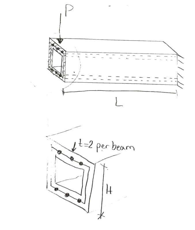
2020_10_05_13.48_Office_Lens_t85tkj.jpg

To me it looks as if the stresses from the outer profile must be transferred to the inner profile through the spot welds, which could reduce the load that the profiles can withstand.
[ul]
[li]What theories are of importance to analyzing this situation? (e.g. Grashoff?)[/li]
[li]Will the spot welds be a limiting factor to the size of P?[/li]
[li]How would you go about analyzing this scenario, if both the displacements and P_yield is of importance?[/li]
[li]How do you calculate the max value of P?[/li]
[/ul]
The scenario left me curious, as I have barely any idea how to answer his question.
 
Replies continue below

Recommended for you


If the loading were pure moment,( V=0 ). There would be no difference with spot welded case and without welded case and the Euler Bernoulli beam will be valid.
However, the load is a vertical load at tip and the shear is constant for all the length and V=P.
If we ignore the effect of shear deformation assuming moment will govern,
The tip deflection and rotation of beam for composite case, inner tube, and outer tube will be similar. (Since the force will be distributed acc. to bending stiffness )..

If we add the shear deflection effect ( Timoshenko beam ) The tip deflections of composite, inner and outer tube will vary. In order to shift the tip deflection to composite case, a couple moment will develop with shear forces at six spot welds.

Just for info.
Assuming your dimensions, one can calculate and see that the tip deflection and rotation will be the same for the distribution based on bending stiffness (EI) for three cases.

I would like to remind to the commenters of this thread to look ( Timoshenko beam ) in order to see the difference .

Regards.


For the sizes stated, without end welds, the inner tube will feel nothing until the gap is closed. That situation is highly indeterminate, I believe.
 
HTURKAK:
In the case of a point moment there will be additional cross section rotation when considering shear deformations. The vertical displacement will remain unchanged.

In either load case yes when considering shear deformation a couple will need to be formed with the spot welds to maintain deformation compatibility between the cross sections assuming the welds act as rigid attachments.

My Personal Open Source Structural Applications:

Open Source Structural GitHub Group:
 
Given dimensions in quote - 16x16x2 and 20x20x2 don't seem to make a tight fit.
 
nikoD said:
I have a friend who asked me how I would go about analyzing the max value of P in the situation shown in the picture.
Two steel profiles are fitted into each other. Both are fixed to the support, but the beams are only connected to each other with spot welds at the beams' ends.

The spot welds will make no difference.

Pu = Fy(Z1 +Z2)/L where Pu is the ultimate load, Fy is the yield stress, Z represents plastic modulus and L is span.

The members will actually carry more load, because (a) ultimate stress in steel is substantially higher than yield stress and (b) span length decreases as the double beam deflects; however development of full plastic moment at the support of a cantilever is normally considered failure by structural engineers.

BA
 
r13 said:
Given dimensions in quote - 16x16x2 and 20x20x2 don't seem to make a tight fit.

I didn't know such sizes were available, but HSS20x20x2 would have clear inside dimensions of 16x16. I would not volunteer to put the smaller HSS inside, however.

EDIT: I guess I would have to put the larger HSS 20x20x2 over the smaller one in order to weld the latter. I would not volunteer for that job either.

BA
 
IDS & BA,

Thanks. Slip of mind. Must be COVID-19 to blame :)
 
The spot welds will make no difference.

Assuming frictionless between contact surfaces, without the weld, slip will occur. The displacements will not conforming to each other, and plane does not remain plane after loading/deformation. I am not certain on how the ultimate state looks though.
 
Can't see how you can improve on developing full plastic moment on both HSS shapes at the support point.

BA
 
That's the situation I was afraid to touch. Theoretically, there are quite a few factors will get involved that complicate the issue. Just image two beams stacked together without bond in between...
 
Celt83 said:
In either load case yes when considering shear deformation a couple will need to be formed with the spot welds to maintain deformation compatibility between the cross sections assuming the welds act as rigid attachments.

No, vertical restraint of the inner tube over the full length enforces compatibility of both curvature and vertical shear deflections, without any longitudinal restraint.

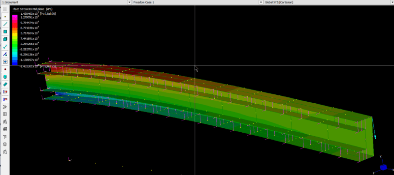
I just did a geometric non-linear analysis of a plate model of half the concentric tubes, with friction element connections between the plates, and friction set to zero:
ConcTubes1_zuzbgi.png


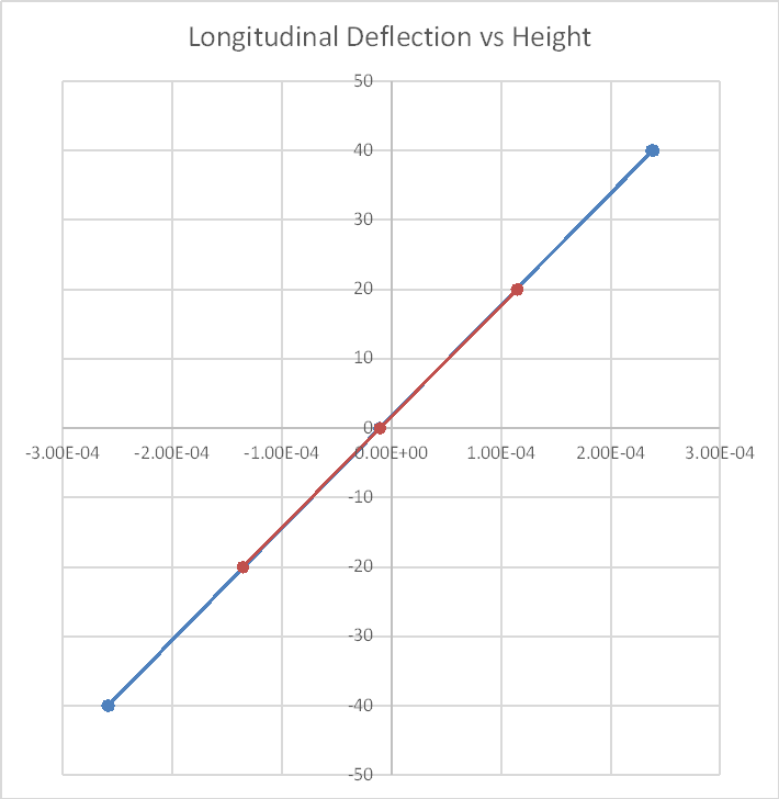
Here is a graph of the longitudinal deflections at the free end of the cantilever:
ConcTubes2_cmwsfm.png


In a real structure there would be variations in the contact of course, but there would also be friction between the contact surfaces.


Doug Jenkins
Interactive Design Services
 
IDS:
Rereading I whiffed on these being sized so the walls are in continuous contact.

Out of curiosity could you run your model with the friction elements only at the free end, on the assumption that there is some vertical space between the tube walls along the span.

My Personal Open Source Structural Applications:

Open Source Structural GitHub Group:
 
Celt83 - Done.

See my previous post for graph of the results :).

The longitudinal deflections at the free end are reduced by about 0.2% in the outer tube, and increased by about 1.5% in the inner tube.


Doug Jenkins
Interactive Design Services
 
Does the end remain plane (all nodes on end plane along a straight line)? Theoretically it shouldn't, provided no friction between the beams.
 
r13 said:
Does the end remain plane (all nodes on end plane along a straight line)? Theoretically it shouldn't, provided no friction between the beams.

Why shouldn't it?

I'd say theoretically it should.

The FEA results are not exactly plane, but pretty close, as you can see from the graph.

Doug Jenkins
Interactive Design Services
 
The title of this thread, Two beams fitted inside each other, spot welded at the ends. What load size can they withstand? is not concerned about deflection or alignment of the ends of members.

The maximum load P carried by the double member is unaffected by the strength of weld at the end of the members; similarly, it is unaffected by a small gap between members. The smaller member could be terminated half way between P and the support without affecting the value of Pmax.

BA
 
BA,

Because deflection is directly related to the member stiffness, which in term is required to proportion the load shared by each member, then the maximum strength capacity can be determined.

 
IDS,

No, vertical restraint of the inner tube over the full length enforces compatibility of both curvature and vertical shear deflections, without any longitudinal restraint.

If the above statement stands, the end, or any, plane should be remain plane, and stress distribution would follow Hook's Law.
 
r13 said:
BA,

Because deflection is directly related to the member stiffness, which in term is required to proportion the load shared by each member, then the maximum strength capacity can be determined.
Deflection and member stiffness are not relevant if the goal is simply to calculate the maximum load the double HSS can carry. The maximum load is the load which causes both members to reach their plastic moment. If one HSS reaches full yield before the other, they keep deflecting until they both reach Mp.

If beam weight 'W' is included, Pu = Fy(Zext +Zint)/L - W/2.


BA
 
Status
Not open for further replies.

Part and Inventory Search

Sponsor