Continue to Site

Eng-Tips is the largest engineering community on the Internet

Intelligent Work Forums for Engineering Professionals

  • Congratulations cowski on being selected by the Eng-Tips community for having the most helpful posts in the forums last week. Way to Go!

Truss - Inconsistent Member Loads 2

Status
Not open for further replies.

bluestar9k

Structural
Nov 11, 2016
31
When cross checking my work between Method of Joints and Sections I found the 2 methods produced different results for the same truss member.

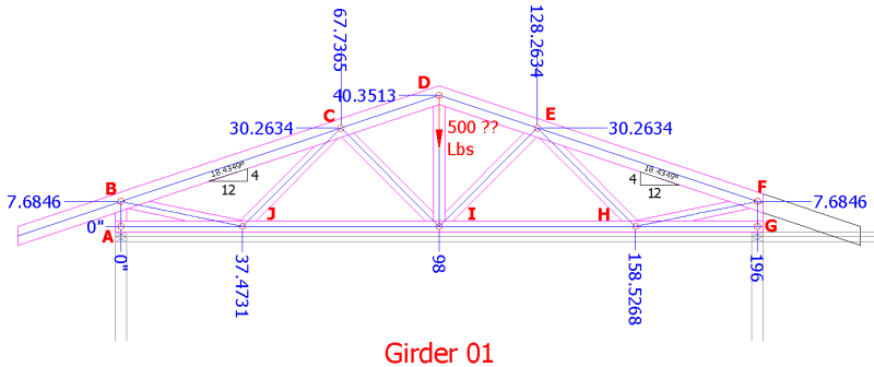
An image of the truss I am designing is attached.

I used an arbitrary reaction force of 529# at Nodes A & G.

Using Method of Joints the computed force in member BC is 1,673#.
Fbc = Reaction Force/sin(18.435) = 529#/sin(18.435) = 1,673#.

Using Method of Sections the computed force in Member BC is 1,038#
Take moment about node J and make a section cut between BC and JI.
Moment about J;  Reaction Force*Distance = Fbc*Distance;  529#*37.47’ = Fbc*19.1’ … Thus Fbc = 1,038#.
19.1’ is the perpendicular projection from BC to J, determined mathematically and graphically.

1,673# does not equal 1,038# and I cannot determine why/where there is an error.
Any insight would be GREATLY appreciated.
 
 http://files.engineering.com/getfile.aspx?folder=8b658cb8-45f2-45a1-a686-de3c3efa71a6&file=Girder01.png
Replies continue below

Recommended for you

Bluestar9k:
That last truss (last post) over the bay window is really an awful abortion. Once you have resolved what you want to do (can do) with the typical truss we’ve been discussing, why wouldn’t you put the header in the bay window opening back at the main wall line, and then use a typical truss over the bay window? Then you stick frame the bay window roof and an interior soffit from the header out to the window, and call it a day. This would also put the main roof reaction back at the main wall line where is can be easily handled instead of out on the bay window cantilever. If you look back at my first post (12NOV16, 04:05) and read btwn. the lines, it pretty much encompasses everything that’s been said since then; although the other guys have certainly added a lot of detailed flesh to the bones. BA’s last post offers another way to skin the cat on the typical truss. Koot has offered some really good sketches and comments on how things actually work. RE: my first post, the last sentence; I was going to suggest two side pls./gussets (.75" plywd.) to cover the area A, B, B + .5, J, A, with BA’s web member B + .5, J. This would resolve the loose heel issue, but probably not as nicely/cleanly as BA’s scheme. It seems to me you have to slow down a bit, really read and think about the ideas presented to you, sometimes read btwn. the lines a bit also. Quit fighting the obvious, and making things difficult/complicated for yourself. You are kinda trying to reinvent the square wheel, which didn’t work so good the first time it was tried.
 
Hey KootK, thanks for the additional information.

Yeah, the nodes C & E respectively were areas of concern and I was going to closely examine the magnitude of the bending moment at those nodes. If necessary I could scab a 2x6 across that node to handle the bending moment.

Oh, your explanation of the dissipation of shear forces in the slider beam just doesn’t feel right with what I understand about forces. I understand an applied force shall remain in magnitude until there is movement in the object where the force is applied or the applied force encounters a reaction force of some magnitude.

Based on the above understanding the image below shows my perception of how the forces in the slider beam dissipate, negating the induced moment.

1444_Slider_jlv5h8.png


Based my understanding of your comment the image below may visually represent your what your comment means.

30_Slider_voy419.png


To me, this just doesn’t seem right but I guess it is possible. So, do you have any reference literature that I could look at to further understand that type of force dissipation

Hey BAretired, thanks buddy for the suggestion. I always find it valuable to see alternatives. Previously, I did apply the member BJ to the drawing and it didn’t look as bad as it was made out to be. Below is an image if you or KootK wanted to comment on it. Also, the slider option may not be off the table if I can fully understand how the shear forces are handled in the beam.

Girder01_pbogkp.png
 
in that model i've expected AJ (and GH) to have zero load.

another day in paradise, or is paradise one day closer ?
 
Rb1957:
BA suggested the same thing in his post on 13NOV16, 05:17. And, while this ‘zero load condition’ might be technically true from the statics, or truss member loads calculation standpoint, removing member AJ or GH would not be wise. This would still leave the 7.68" high heel members AB and FG loose (stilts which can tip over) and unable to transmit any lateral loads from the roof system down to the top wall plates.
 
OP said:
Hey KootK, thanks for the additional information.

You're welcome.

OP said:
To me, this just doesn’t seem right but I guess it is possible.

See the sketch below for the statics of the slider business. Uniform shear. I took a few minor simplifications in order to keep things clean. This is also why top chord sliders are more popular than bottom chord sliders. The force P pushes into the top chord rather than pulling away from the bottom chord which is more reliable and demands less of the plate connections.

If you did a similar analysis on your proposed bottom chord slider, the shear stress would rightly be (1444 lb * 7.25 in) / 36 in.

OP said:
do you have any reference literature that I could look at to further understand that type of force dissipation

Indirectly, sort of. See the snip below from the TPIC doc which refers to the slider conditions. In my opinion, it describes delivering the chord force over the length of the slider, albeit never perfectly uniformly.

Capture_01_enozxn.jpg


Capture_01_wpmopc.jpg


I like to debate structural engineering theory -- a lot. If I challenge you on something, know that I'm doing so because I respect your opinion enough to either change it or adopt it.
 
i didn't say it'd be a better structure (without AJ and GH).

if you add a side load at A, maybe 5% (10%?) of the reaction at A, then you have load in AJ; but I was assuming that the theoretical model would say vertical reaction at A.

another day in paradise, or is paradise one day closer ?
 
If you are considering it as a truss, then CJ and EH are zero force members. Removing these from the analytical model then reveals CE and EI are zero force members. With those now removed, DI is also found to be a zero force member. For load applied to the top chords, then you have bending ad compression in the chords (depending on load placement). lets assume the loading is such that you have only compression in the top chords. You will definitely have bending in AB of FG. Adding in
 
Status
Not open for further replies.

Part and Inventory Search

Sponsor