Continue to Site

Eng-Tips is the largest engineering community on the Internet

Intelligent Work Forums for Engineering Professionals

  • Congratulations waross on being selected by the Eng-Tips community for having the most helpful posts in the forums last week. Way to Go!

Truss - Inconsistent Member Loads 2

Status
Not open for further replies.

bluestar9k

Structural
Nov 11, 2016
31
When cross checking my work between Method of Joints and Sections I found the 2 methods produced different results for the same truss member.

An image of the truss I am designing is attached.

I used an arbitrary reaction force of 529# at Nodes A & G.

Using Method of Joints the computed force in member BC is 1,673#.
Fbc = Reaction Force/sin(18.435) = 529#/sin(18.435) = 1,673#.

Using Method of Sections the computed force in Member BC is 1,038#
Take moment about node J and make a section cut between BC and JI.
Moment about J;  Reaction Force*Distance = Fbc*Distance;  529#*37.47’ = Fbc*19.1’ … Thus Fbc = 1,038#.
19.1’ is the perpendicular projection from BC to J, determined mathematically and graphically.

1,673# does not equal 1,038# and I cannot determine why/where there is an error.
Any insight would be GREATLY appreciated.
 
 http://files.engineering.com/getfile.aspx?folder=8b658cb8-45f2-45a1-a686-de3c3efa71a6&file=Girder01.png
Replies continue below

Recommended for you

Bluestar9k:
It appears that you are trying to design a truss with energy heels over the truss bearing points, the exterior walls. I think you can fix your truss design and analysis problem by making the heel heights more the 7.68" high, thus more depth for insul., and then by adding two more diag. web members at the heels, BJ & FH. This will make the complete truss which SRE says you are missing. I suppose you could try to make some sort of a moment/force connection from BC through AB and to AJ with heavy side plates (plywd., stl. pls., or heavy truss nailer pls.), but it’s probably more work than it’s worth.
 
Hey Guys, thanks for your input!

I’m not sure the truss configuration is the issue. Consider the following truss types in the first attached image. (This is NOT meant to be an advertisement for MiTek but a visual representation of the many different truss types.)
Tail Bearing
Flat
Sloping Flat
Parallel Chord Scissor
Parapet
Sloping Parapet
Cape

Also consider the bearing conditions in the second image. Sorry, I don’t recall the source information for this image.
Top Chord Bearing
Mid Height Bearing
Leg Thru Bearing

Also, I was under the impression that Method of Joints and Method of Sections was applicable to any type of Truss configuration, traditional or not, provided the requirement of each method was respected.

With that said, I suspect there was something wrong with my approach to the Method of Sections (MoS). The one thing that bothered me with my approach to the MoS was the axial forces in member AB. I may have wrongly rationalized that the axial force was not applicable because I considered the “Section” as monolithic block (3rd attachment) and all forces within the section were self-contained. Since the axial force of AB did not pass through Node J this may have been inconsistent with the requirements of MoS.

This point was validated when I moved the bottom chord up 7.6846” so that it intersected with node B as suggested by SRE. When the analysis of MoS was performed the force for Fbc was 1,673# and that value was consistent with the Method of Joints (MoJ).

Now, that Fbc was confirmed I moved the bottom chord back to its original position and performed a MoS again and found there was an imbalance in the sum of moments of 12,129 ft-#. I suspect this imbalance comes from the axial force in member AB since this was the only thing that changed. However, the axial force in member AB was determined to be 309# by way of MoS and this is not consistent with the 529# force in member AB as determined by the MoJ.
Moments about J = Reaction Force*Distance + Fab*Distance = Fbc*Distance
529#*37.47’ + Fab* 37.47 = 1673*19.1’  Fab = 324#

Axial Force Member Fab = 324# vis MoS
Axial Force Member Fab = 529# vis MoJ

Again, inconsistent member forces…


Attachment 2

Attachment 3
 
looking at your first post,
this is not a traditional truss 'cause you need members AB and GF to react moments; ie the load in HG gets into EF by bending FG.

I'd also extend EF and BC down to the level of AG

simpler would be to add member BJ and FH ... now it's a traditional truss (ie axially loaded members only).

another day in paradise, or is paradise one day closer ?
 
It's like this:

1) The issue that you're having is related to truss configuration in the sense that a pin connected raised heel joint as you've drawn it cannot transmit a horizontal force component between the top and bottom chords. And that's a big part of conventional truss action.

2) Because of #1, the method of joints applied to joint B yields a force in member BC of zero. At least that's he case with standard assumptions of pinned joints and loads applied only at the joints. And the method of sections is technically invalid because the rigid bit that you've sectioned is actually a mechanism at the heel.

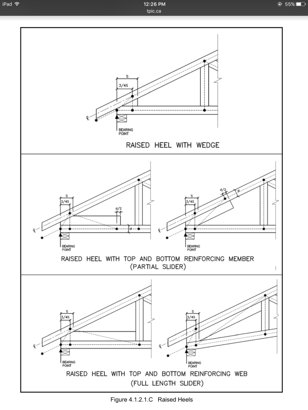
3) The Truss Plate Institute's design standard provides "fictitious heel joint" models that the truss industry uses to restore triangulation to heel configurations like this. You may want yo take a similar approach.

4) 1673# is the "right" answer in this case and will be valid once the heel joint issues are resolved. In physical terms, that probably means adding a slider to the joint. With a fictitious heel joint model in play, the method of joints should produce the same result.


I like to debate structural engineering theory -- a lot. If I challenge you on something, know that I'm doing so because I respect your opinion enough to either change it or adopt it.
 
Just looking at the first post attachment tells me "good luck is needed for who ever gets it." And good luck to the designer when he is sued.
 
Most of the fictitious heel models do, in fact, reqruire moments in the chords.

IMG_0353_tddwic.png


I like to debate structural engineering theory -- a lot. If I challenge you on something, know that I'm doing so because I respect your opinion enough to either change it or adopt it.
 
if he extends AJ and BC until they intersect at X, then can he solve the bermuda triangle ABX by hand.

extend AJ, delete member BJ, and solve the traditional truss.

now you know the shear (transverse) load in BJ (the load in AJ). the simplest model says BJ is cantilevered at B. a sensible model for BJ would be a beam doubly fixed but the moment at J is harder to balance.

another day in paradise, or is paradise one day closer ?
 
WOW!!!
Another plausible solution!
That is why this site and the members are the greatest!!

I was prepared to consider the diagonal member as proposed by dhengr and rb1957 or the slider as suggested by KootK both of which were good solutions.

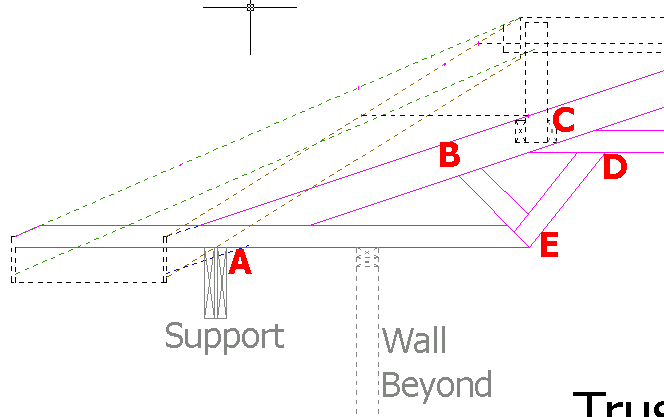
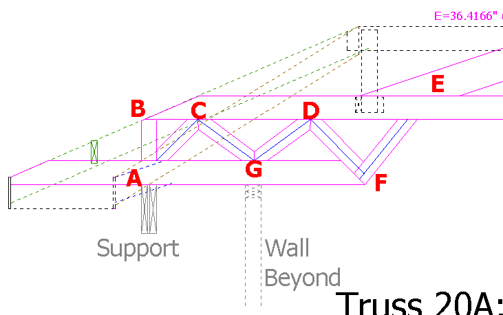
However, in my situation, I think the extension of member AJ to intersect with the TopC is the best because of simplicity and cost of materials. Incidentally, I had already extended the AJ member to intersect the TopC on some trusses which span out over Bay Windows (see attachment) and I had toyed with the idea of doing the same for all trusses for consistency sake and I did have the clearance to do so; but, I elected not to do it because of the presumed lack-of-necessity and increased material cost. Now, to eliminate the moment at node B (which has nagged me for some time) the extension is a terrific idea.

Humm, the only concern I have is if the intersection of the TopC and BotC is labeled “X” thus making the triangle ABX then what will be the horizontal, vertical and axial forces between BX?

If the vertical load is carried by AB and the horizontal load will be transmitted to AJ can ONLY horizontal load be transmitted between BZ with no axial load? If so what kind of load would it be on member BX,… diagonal shearing load?
 
 http://files.engineering.com/getfile.aspx?folder=8eb5d3e9-4e5a-427e-9c56-fc5aca4fc942&file=TrussBayWindow.png
OP said:
However, in my situation, I think the extension of member AJ to intersect with the TopC is the best because of simplicity and cost of materials.

Be careful with this. Truss designers don't usually do this as a stand alone solution because it results in having to carry the entire truss reaction through the bottom chord in shear. That can be a problem.

OP said:
Now, to eliminate the moment at node B (which has nagged me for some time) the extension is a terrific idea.

Note that the moment in the joint exists no matter what solution you pursue. By running the bottom chord out, you put the moment in the bottom chord and, inadvertently, the heel plate which will only be designed for tension and shear.

I like to debate structural engineering theory -- a lot. If I challenge you on something, know that I'm doing so because I respect your opinion enough to either change it or adopt it.


If member AB still exists in the system then does it not carry the full reaction load? And the BotC only sees and handles the horizontal load?

If all of the forces at a node are balanced how can there be a moment?

Oh,... any comment about the type of forces acting on the TopC between BX?
 
By retaining member AB, you are still left with polygon ABCJ which is unstable. The Method of Joints and the Method of Sections are based on the assumption that all joints are hinged; a four sided polygon with hinged joints is not stable.

In reality, the joints are not all hinged, so you could possibly make it work by considering bending in some or all of the members but you cannot analyze them with the methods you have been using. You could analyze them using a frame analysis.

Alternatively, you could add member BJ as suggested by dhengr. If you do that, member AJ will be redundant as it will have zero force but the structure will be stable.

Theoretically, you could remove the redundant member AJ but from an aesthetic point of view, it may be preferable to retain it.


BA
 
OP said:
If member AB still exists in the system then does it not carry the full reaction load

It will carry the load in bearing. The question is whether or not it will also carry the load in bending and shear. Generally, we hope not.

OP said:
If all of the forces at a node are balanced how can there be a moment?

You can have no moment at a joint but still moment in the adjacent members. As with most things, there's no free lunch. Your top and bottom chord centrelines do not intersect above your bearing points. That eccentricity will manifest itself someplace no matter what clever tricks we attempt.

OP said:
Oh,... any comment about the type of forces acting on the TopC between BX?

With triangle ABX in place, your truss is statically intererminate and your forces should come from a a frame analysis rather than a truss analysis. Between B and X, your top chord would see a bunch of shear and bending in addition to compression.

I like to debate structural engineering theory -- a lot. If I challenge you on something, know that I'm doing so because I respect your opinion enough to either change it or adopt it.
 
rb1957 said:
if he extends AJ and BC until they intersect at X, then can he solve the bermuda triangle ABX by hand.

extend AJ, delete member BJ, and solve the traditional truss.

This is bad advice and should be ignored. You cannot solve the triangle ABX by hand without resulting in bending of the bottom chord. The force in BX has a vertical component which must be resisted by bending of the bottom chord.

Deleting member BJ will not result in a traditional truss.

BA
 
This Grasshopper now sees the error in his ways, oh humble Masters.

The most profound and convincing information for not using the extension of AJ to the TopC came from BAretired when he pointed out the unstable polygon ABCJ. I didn’t notice that late last night and didn’t notice that first thing this morning. Also, KootK points out the complexity of forces and moments about the ABX triangle.

It seems all of this can be resolved by falling back to the proposals of adding member BJ and FH or using a slider between nodes AB and FG. It did not take much consideration to see that when adding tension member BJ that member AJ could be eliminated; however, AJ is required as a support for the gypsum board.

I would appreciate if you would also take a glance at the truss over the bay window and point out anything that might bother you. Your insight has proven to be most valuable and appreciated.

1st Consideration
TrussBayWindow_gp3xsm.png


Alternate
TrussBayWindow-Alternate_pbkkyn.png
 
Triangle ABX is only unstable when performing a pure truss analysis. Considered as a frame, with chord moments, ABX is not just stable but one of the TPI recommended model analogs.

As a truss designer:

1) your heel height is usually dictated by others and there is little room for negotiation.

2) unless your heel height can be at least 16", prividing the extra diagonal web to triangulate the heel can be impractical. You end up with a single cut member on the exterior end and a 2 degree scarf cut on the interior end. It's no fun for the sawyer and, when all is said and done, the last two feet of the truss become solid lumber. Little different from the slider mechanically.

The two trusses in your latest post both seem pretty sketchy to me. They both have pinch points where there will essentially be no true truss action and only chord bending. I'd recommmend:

1) additional truss support.
2) more workable coffer/roof lines.
3) top chord bearing trusses if they work.
4) dealing with the more complex areas using hand framing.


I like to debate structural engineering theory -- a lot. If I challenge you on something, know that I'm doing so because I respect your opinion enough to either change it or adopt it.
 
With respect to the very first truss (non-BayWindow).


KootK said:
unless your heel height can be at least 16", prividing the extra diagonal web to triangulate the heel can be impractical. You end up with a single cut member on the exterior end and a 2 degree scarf cut on the interior end. It's no fun for the sawyer and, when all is said and done, the last two feet of the truss become solid lumber. Little different from the slider mechanically.

Yeah, because of the very shallow angle, 11 degrees, I first elected to consider a horizontal 2x6 slider between AB and J. However, the horizontal shear forces of member BC will be around 1,587 (1,673*cos(18)) and this induces shear forces parallel to the grain of the slider. When looking at the unadjusted capacity of the wood (S.Pine) the sheer exceeds the capacity of the wood so I moved on to the BJ beam consideration.
Fv=175; A=8.25; …175*8.25= 1,444 capacity (unadjusted).

The BJ beam carries the tensile load in a full axial condition and the tensile strength is around 3.4 times stronger so no problems are anticipated after TPI/NDS adjustments. Yep, the high angle cuts to make this beam fit are not desirable but right now I do not know a better solution.


With respect to the BayWindow Truss.

The bending moment about node A has always been my concern with this truss.

Kootk said:
1) additional truss support.
2) more workable coffer/roof lines.
3) top chord bearing trusses if they work.
4) dealing with the more complex areas using hand framing.


1. A full height ceiling was desired in the bay window area negating the additional support possibility.
2. Not quite sure what is meant with this comment. The roof slope is set and the coffer ceiling is set.
3. The “1st Consideration” Truss can easily be changed to a true TopC bearing truss. This might be better because the compressive strength parallel the grain is somewhere around 2.5 greater than perpendicular to the grain. Granted the roof slope needs to be considered in the capacity calculations.
If a TopC bearing truss is utilized how are the horizontal forces in member AC picked up?
4. Again, not quite sure which areas you are referring to. I venture a guess you mean the AED section.


The trick with the slider is to recognize that the entire length of the slider can be mobilized to resist the horizontal shear. In your case, the shear area will be something like 1.5" x 36" bringing your shear stress down to about 30 psi.

In the bay window trusses, the A joints aren't the problem. It's joints C & E in the first and second sketches respectively. High chord bending stresses at those locations.

I like to debate structural engineering theory -- a lot. If I challenge you on something, know that I'm doing so because I respect your opinion enough to either change it or adopt it.
 
Status
Not open for further replies.

Part and Inventory Search

Sponsor