Tek-Tips is the largest IT community on the Internet today!

Members share and learn making Tek-Tips Forums the best source of peer-reviewed technical information on the Internet!

  • Congratulations MintJulep on being selected by the Eng-Tips community for having the most helpful posts in the forums last week. Way to Go!

Truss connection 2

Status
Not open for further replies.

BAGW

Structural
Joined
Jul 15, 2015
Messages
392
Location
US
Hi,

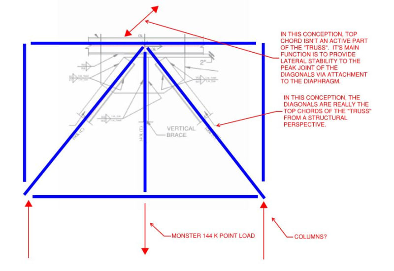
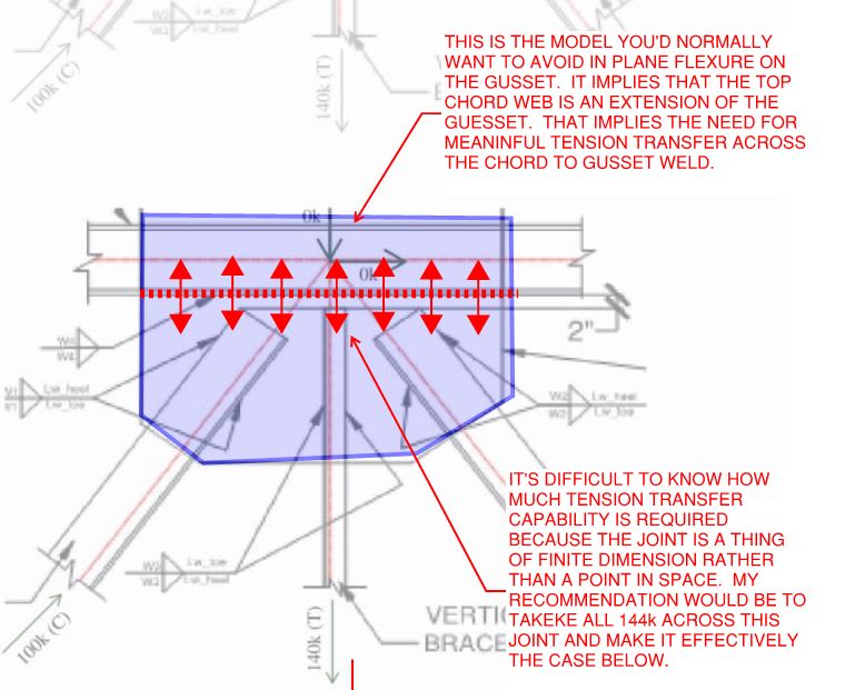
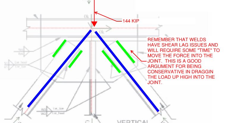
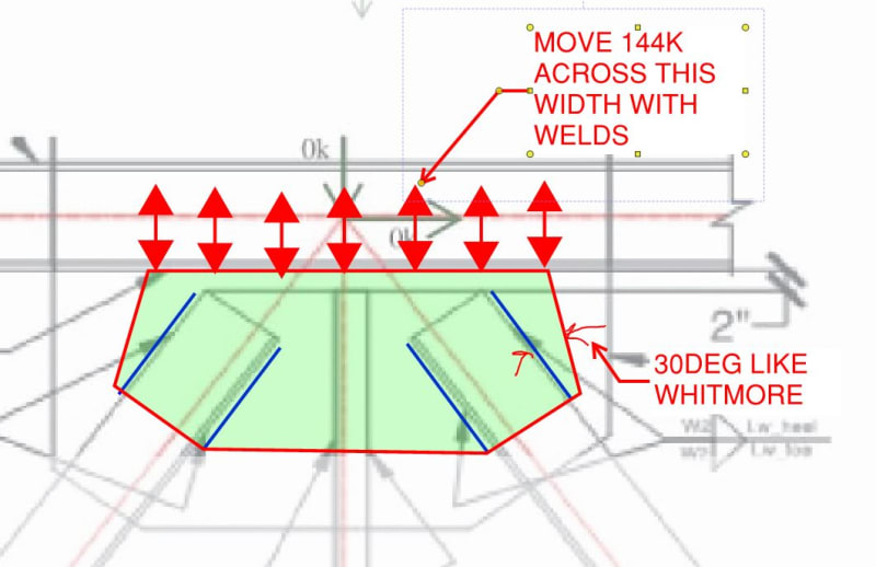
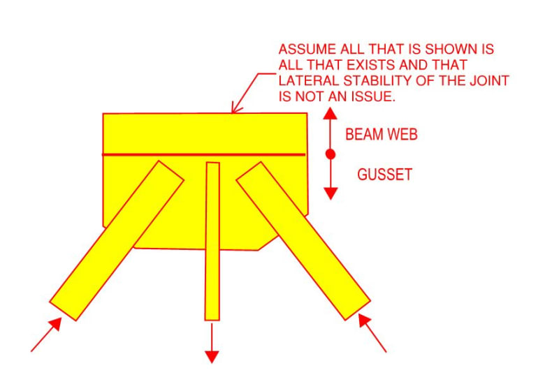
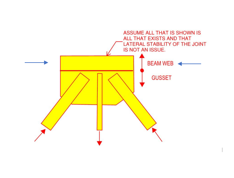
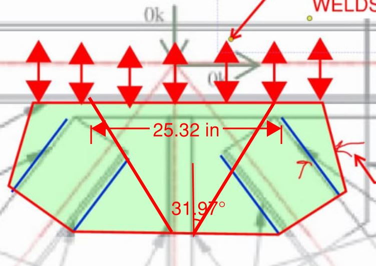
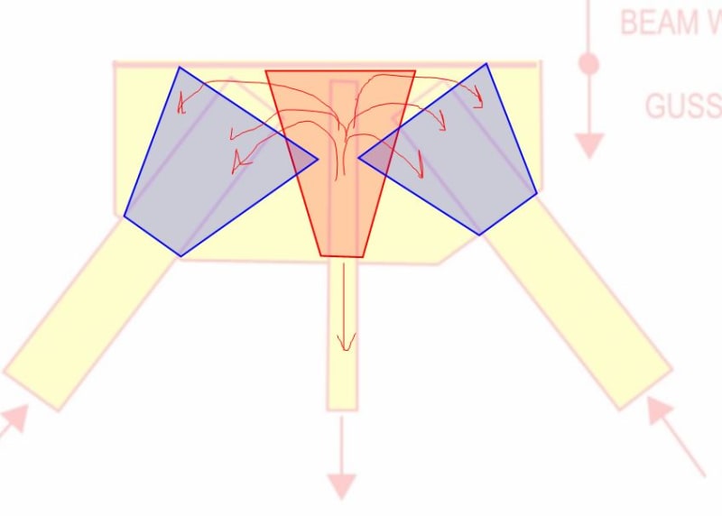
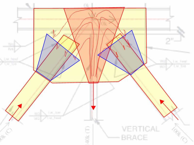
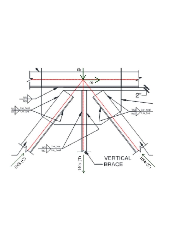
See image below. The diagonals are in compression and vertical is in tension. When I sum up all the components for the gusset to chord design, the forces adds up to be zero. This does not make sense. How do you come up with the forces for the gusset to chord design? I dont think splitting the plate into half and checking for the local forces is correct.

Any thoughts. Can I just design for 140k of vertical force?

Thanks
Document1_hbduye.jpg
 
Pay attention to PRIYECTOR's response, which contains very important message.

Also, if the chord can be utilized, why not reverse the diagonals to pointing down (like V), and eliminate the middle vertical member.
 
You mention this is a truss connection... Does that mean there are more connections like this? I ask because the other connections will have shear.
 
@OP:

Detailed aspects of the connection design aside, I feel that it's absolutely critical that you (and we) truly understand the statics of the situation accurately. That, particularly if you're functioning as the delegated connection designer. If things balance to zero that's peachy; just make damn sure that isn't a consequence of a miscommunication or an error on somebody's part, however, before you run with a zero / nominal demand weld. I very much applaud your effort to resolve the nagging concerns that you have for the top chord well here. As you'll see later, I think that concern is well founded.

What is the situation here in terms of what the rest of the truss looks like? Dave's read on it was a clever interpretation. I've proposed another below. As BAret mentioned, that 144K concentrated load is a monster and draws the eye. That's not normally what one would expect to find at the middle of your average truss.

c01_v0gltt.jpg
 
This is what I propose for the actual doing of it.

c01_c0jixp.jpg
 
Whats the chord size?
Throwing stiffeners at certain locations and / or stiffening the web by doubler plate would make it more safe.

As for the remaining connection, ( gusset thickness and weld size) I would design them based on the worst load case.(140 k comp. Or 100k T).
 
I guess I'm not seeing the load, introduced by the vertical member (as originally shown) and being reacted by the two diagonal members, being applied to the upper chord ?

Don't these three members balance one another, in the y-direction, so the load applied to the upper chord is 2 70k shears (the upper chord is in compression, 70k) ?

another day in paradise, or is paradise one day closer ?
 
rb1957 said:
I guess I'm not seeing the load, introduced by the vertical member (as originally shown) and being reacted by the two diagonal members, being applied to the upper chord ?

I agree, no load gets transferred to the beam in the macroscopic sense that it would produce bending stresses in the flanges of the beam, end reactions etc. Rather, it is my contention that a conventional design approach for the gusset requires that the beam web locally function as part of the gusset.

Imagine the situation shown below where there truly is no beam other than the chunk of web that I believe needs to be utilized by the connection. I would be just fine with this situation as shown.

One of the keys to steel connection design is to be able to shelve the part of ourselves that thinks in terms of sticks and nodes and, rather, think in terms of parts and pieces with finite dimensions.

c01_dvkrsz.jpg
 
I can understand KootK's argument; beam web is deemed to be an extension of the gusset plate. But I can't see anything wrong with sizing the gusset plate so that it can handle the forces coming into it by itself, without reliance on the chord. In that case, the weld to the chord would be nominal. Welding to develop the full 140k tension seems to me like overkill.

BA
 
I guess I didn't get that from your previous post.
I'd add two more loads (for the upper chord compression) …
Screen_Shot_06-18-20_at_03.41_PM_2_bh950s.png


there's a question … what is the upper chord compression ? 70k ?
another day in paradise, or is paradise one day closer ?
 
BAretired said:
But I can't see anything wrong with sizing the gusset plate so that it can handle the forces coming into it by itself,

Not so much wrong as inefficient, unconventional, and producing less predictable behavior. Try this:

c01_z0qeki.jpg
 
rb1957 said:
I'd add two more loads (for the upper chord compression) …

1) Maybe, maybe not. OP didn't say.

2) Axial stresses in this situation if present, would be highly unlikely to have a material effect on the connection design.
 
As mentioned before, the free edge of the gusset plate subjects to a compression force due to the thrust from the diagonals. The 140 kips tension is balanced by the vertical shear forces within the plate. Thus, I would conservatively, but not overly, design the chord-plate connection for the horizontal compression force near the free edge, 70 kips.
 
BAretired said:
Welding to develop the full 140k tension seems to me like overkill.

Isn't it like an 1/8" weld? If it's overkill, it's cheap overkill.

c01_ptmhtu.jpg


c02_shth9l.jpg
 
Although I think that I like it better like this which would imply 3/16" welds +/-.

c01_ctwe6l.jpg


c02_banwiz.jpg
 
KootK,

It's not really a big deal either way. I would expect the gusset plate carrying that kind of load to be 1/2" minimum, so bending deformation is negligible and plate buckling is not likely to be a factor. The fabricator, when determining weld size probably looks at the net force between chord and plate, so in this case he may come up with a stitch weld rather than a continuous one and for that reason, I would prefer to rely on the gusset plate alone rather than the combination of chord and plate.

BA
 
Whether it's a big deal numerically or not, I think that it's fundamentally poor connection design to not take the opportunity to eliminate in plane bending from the gusset force set when it would cost next to nothing to do so. If you want to design the gusset for bending and buckling in addition to that, all the better.

With regard to OP's original question, I feel that it's important to acknowledge that his instincts about the need for some degree of force transfer into the beam web were not, fundamentally, in error. Quite the opposite.
 
This part's a bit touchy feely but I also think that a gusset that doesn't make it to the point of concentricity struggles to transfer the forces around in a way that respects the distance over which it takes to mobilize those forces given shear / tension lag etc. In this respect, I like the feel of the taller gusset much better. It's difficult to even really know how to check bending on something like this given that Bernoulli assumptions would be junk at such proportions.

c01_nvyoi3.jpg


c02_ctn9ud.jpg
 
KootK said:
If you want to design the gusset for bending and buckling in addition to that, all the better.

I do, and would have no objection to excessive welding between plate and chord.

BA
 
Status
Not open for further replies.

Part and Inventory Search

Sponsor

Back
Top