RWelch9,
Here are a few thoughts.
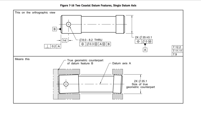
Your drawing specifies 2X and a position tolerance on the OD's. This means that:
-The two OD's are treated as two distinct features.
-When labeled as a datum feature, this creates a multiple datum feature (2009) or a common datum feature (2018).
-For the RMB datum feature reference, there would be two cylindrical simulators/TGC's that are fixed in location relative to one another (i.e. coaxial in this case).
-In 2009, "The datum feature simulators shall expand or contract simultaneously from their MMB to their LMB until the datum feature simulators make maximum possible contact with the extremities of the datum feature(s)."
-In 2018, "The true geometric counterparts shall expand or contract simultaneously from their worst-case material boundary to their LMB until the true geometric counterparts make maximum possible contact with the extremities of the datum feature(s). When irregularities on the feature(s) may allow the part to be unstable, a single solution shall be defined to constrain the part."
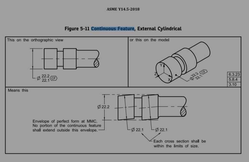
If the drawing had specified <CF> instead, then it would mean:
-The two OD's would be treated as one "continuous" feature.
-For the RMB datum feature reference, there would be one cylindrical simulator/TGC.
-The simulator/TGC is the smallest circumscribed perfect cylinder that makes maximum possible contact with the datum feature surface
The two OD's in your drawing have the same nominal size and size tolerance. This avoids additional cans of worms that we would have to open if they did not.
Evan Janeshewski
Axymetrix Quality Engineering Inc.