Continue to Site

Eng-Tips is the largest engineering community on the Internet

Intelligent Work Forums for Engineering Professionals

  • Congratulations waross on being selected by the Eng-Tips community for having the most helpful posts in the forums last week. Way to Go!

Trenwall Pre-Cast Cable Raceway/Trench and Cable Ampacity

Status
Not open for further replies.

7carisfast

Electrical
Jun 15, 2004
48
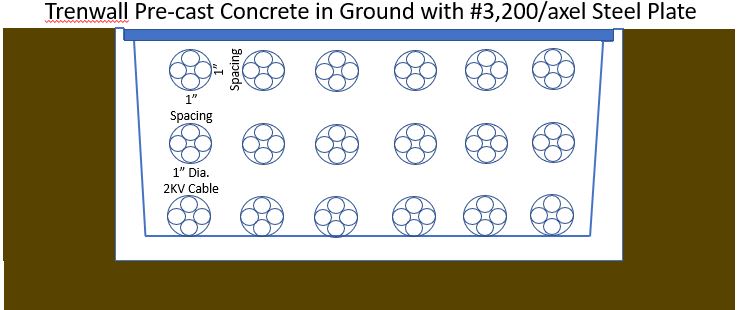
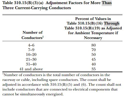
Per the sketch below, can someone confirm these cables only need a 0.80 de-rating factor (Table 310.15(B)(3)(a) since there are 4 carrying conductors per cable (DC application, 2-1500V+ and 2-1500V -) as long as 1" cable diameters are spaced at 1" intervals via intermittent plastic cable supports for spacing? Tench length will be double lane (so estimate that at 24 feet. Then, a vented cover can be used.


tren_vmrzye.jpg
 
Replies continue below

Recommended for you

First of all no correction for number of loaded cable-more than 3-is stated in NEC for cable in underground duct bank. The correction factor-if any- is applicable for a standard [as per NEC] duct bank arrangement and standard cable. No such arrangement it is described in Art 310.60 [15 ducts 1" clear distance]
According to IEEE 835/1994 the maximum number of ducts per a duct bank is 9 [type d] .However there is only 3 cables per duct. For 350 MCM [175 mm^2] copper at 25oC earth temperature [RHO=90] 212 A [100% LF] and for 60 Hz [not for d.c.]. The distance center-line-to-center line is 190 mm .The clearance depends on duct outside diameter [for instance for 4" pipe of 4.5" outside diameter the clearance is 3"].
In my opinion your cable is 1*185 mm^2 copper [class 5 stranded] EPR/Rubber insulated and jacketed. In open air carrying current capacity is 510 A [at 30oC Air] 3 cables in trefoil. According to my calculation [according to IEC 60287] for your arrangement 135 A it could be the ampacity.

 
Thanks 7anoter4. But Table 310.15(B)(3)(a) is required to be taken into account, as all references in the NFPA 70 for conductor ampacities for 1/C or 3/C. This is why the table is entitled "...More Than 3..." Since there 4 current carrying conductors we need to de-rate the cable by at least 80%. In this scenario, I am looking at 4-4/O conductors with ground. 2 Conductors for (+) and 2 are for (-).

tt_jgnf5f.jpg
 
Sorry 7carifast but the Table 310.15(B)(3)(a) is referring to Percent of Values in Table 310.15(B)(16) Through Table 310.15(B)(19) only. Cable ampacity in duct bank are in Table 310.60(C)(77) through Table 310.60(C)(85)[and for cable with rated voltage from 2000 to 35000 V 60 Hz ]. The only correction permitted for these tables is for Burial Depth of Underground Circuits. For cable above 2 kV rating in AIR a correction factor for air temperature different than 40oC is permitted.
In Annex B correction factors for different temperature are inserted at lowermost part of each table
Also in each table 3 RHOs[60,90,120] are considered but still no recommendation for correction factor for more than 3 loaded cables in a duct.
However ,there is not a duct bank for more than 6 ducts- in NEC- and no more than 3 cables per one duct.

 
I think I wrong understood your problem.
I considered this installation as 3*6 ducts[or pipe] in a concrete duct bank in ground.
On the second glimpse I think there are 18 cables of 4 conductors [not in pipe or ducts] of 1” overall diameter each in air in an empty pre-casted trench on plastic support [the same support we use for ducts in a concrete duct bank] .
In this case the calculation is different.
First no arrangement like this is standard in NEC so no reduction factor could be applied anyway.
I have to think how to calculate it. Cable details as conductor, insulated core and jacket diameter is required and the materials also. It is possible to consider the trench as ventilated [as open trench then]?
The actual inner dimensions of the trench may be useful.
 
Thx 7anoter4. I appreciate it. I didn't know if there was an easy way for not. Open cover might be an idea, just worried about truck traffic and dirt as this is a dirt road. The only way I think the correct de-rating factor might be able to be calculated would be via the SKM module or such. I was hoping if the cables where distanced some diameters away from one another, no de-ratings would be required.
 
SKM program it is a good idea.
Following Siemens publication: Power Cables and Their Application, 3rd Edition by Lothar Heinhold/Reimer Stubbe (Editors) chapter 18.5.1 Unventilated Channels and Tunnels the problem may be divided in two parts.
The first part is the individual cable heating calculation [in air, as usual: this according to Neher&McGrath theory or IEC 60287] and second part the closed air heating. The second part is presented in Siemens above publication and schematically so:
Fig18_48_mg5qlj.jpg

An approximate calculation for 18 cables of 4*#3 copper conductor EPR [90oC rated] at 110 A
the air temperature was 79oC and the conductor 90oC.
 
Revising the calculation program for 4*#3 copper conductor XLPE insulated and PVC jacketed cable
in a 20*12 inch pre-casted trench in earth of 100 RHO and 30oC top earth temperature, covered by 200 mills steel plate, 3 rows of 6 cables in each row the air steady state temperature was 51 oC at 94 A per conductor.
Since NEC does not present a solution for this arrangement I used DIN-VDE 0276 standard [from ABB
Switchgear Manual 11 edition vol.13].The cable close to 4*#3[26.67 mm^2] was 3*25mm^2 XLPE insulated PVC jacketed on 3 rows racks 6 cables per row at 50oC air.
For a single cable the ampacity at 30 oC in still air is 145 A. For 18 cables 1” apart 0.93 factor and for
50oC air another 0.82 factor. At 600/1000 V DIN-VDE consider for 4 conductors the same ampacity as for 3 conductors. How ever since the fourth conductor is neutral then low loaded in our case 4 loaded conductors
another 0.8 factor is required. Finally the ampacity will be 145*0.93*0.82*0.8=88.14 A.
However, since the d.c. resistance of #3 copper conductor at 90oC is 0.84 ohm/km and of 25 mm^2 copper
is 0.897 a new correction factor of √(0.897/0.84)=1.033 .That means 88.14*1.033=91 A.
As recommended in DIN-VDE 0276-1000 :
Load reduction is not required where horizontal or vertical spacing to adjacent cable is at least twice the cable diameter- that means at least one diameter clearance [see ABB Switchgear Manual ed.11 vol.13 Table 13-53].
 
I must inform you that no matter what value is obtained from calculation NEC does not allow more than 60oC conductor temperature for 100 A or less [See Art.110.14].Then according to 310.15(B)16 for 60oC only 85 A is permitted.[peace]
 
Status
Not open for further replies.

Part and Inventory Search

Sponsor