Continue to Site

Eng-Tips is the largest engineering community on the Internet

Intelligent Work Forums for Engineering Professionals

  • Congratulations cowski on being selected by the Eng-Tips community for having the most helpful posts in the forums last week. Way to Go!

Tree Canopy Walkway

Status
Not open for further replies.

YuleMsee

Structural
Apr 8, 2018
68
Client got inspiration from this project (Kirstenbosch National Botanical Garden).
IMG_3175_1_asob5s.jpg

7c2571ebaac5eff773f6546698b29224_mlqskt.jpg

IMG_3174_2_ksluk5.jpg

IMG_3170_vtqde5.jpg

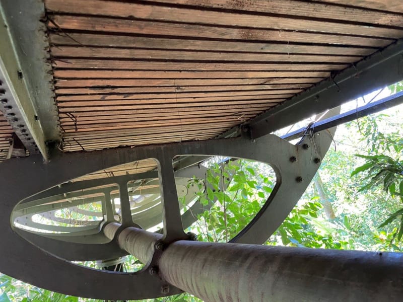
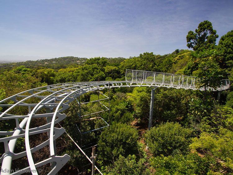
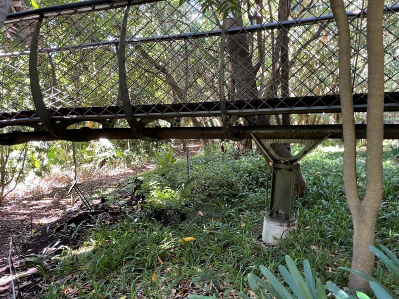
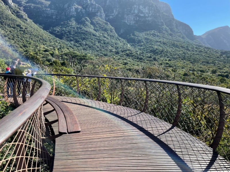
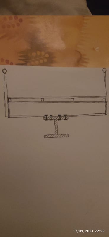
Problem, no fabricator/foundry in my country is interested in making those curved members( project isn't big enough. (wonder how the South Africans did it, or are those sections used for other purposes there?)
So now I'm forced to assume architect role and come up with something that can be done using your everyday sections.
I invite you to join me in elementary architecture. My first go at it,
IMG_20210917_222939_khjdfl.jpg
 
Replies continue below

Recommended for you

Nice project. Should be lots of fun. I would suggest a square or rectangular hollow section under the walkway because it has better torsional properties than an open section. For bolted connections to the cross beams, use clip angles each side of the HSS.

BA
 
Yeah agree with BA. Closed section all the way.
 
That is an interesting one. The inspiration pics look like they're built up/laminated plate elements. A decent size burning bed should be handle those no problem, regardless of the size of the project. If you're trying to bend tubes, then I could understand the hesitancy.
 
Looks like a roller coaster track. They always seem to use pipes. More efficient torsionally and probably easier to bend.
 
That 1st photo sure looks like a stress ribbon bridge. Website for Kirstenbosch National Botanical Garden bridge doesn't mention it but it's not very technical, anyway. I mention this because, if it is a stress ribbon bridge, those "pipes" are actually ducts that carry lots of post tensioning tendons. It's basically a reverse suspension bridge. I'm not going to pretend that I have ever designed one of these before but I have studied them as we were gearing up to help a Contractor build one. They are complicated and not very common.

If you design something similar but using only one static strongback member. Definitely agree with everyone else... don't use a Wide Flange, use something with torsional rigidity. You will need to run some in depth vibration analysis to make sure that you don't have any undesirable harmonic phases.
 
YuleMsee - What is the minimum allowable spacing of piers? The closer together, the simpler the solution.

 
You’re client needs to compare apples with apples. As far as I’m aware that amazing looking bridge is all post tensioned. It’s not a ‘pipe’ but a duct housing some very highly tensioned cables.

If you are to do it using standard sections, they will be big, and as noted above I’d go for a hollow section given the massive torsional stresses you’re going to encounter. Ideally I’d make a truss with q triangular cross section like the image below.

A4FD65DE-FE6D-4F66-95FE-5C47DB19D507_alwuxj.jpg


Great project though!
 
It doesn't fit with the typical "stress-ribbon bridge" description, where there is usually a catenary between supports.
 
The 2nd photo most likely is not as that is a small little amusement park bridge in Branson, MO. The one from the Botanical Gardens does have a small catenary drape to it if you look. The spans are not very far so it would make sense if the drape was minimal.
 
I wonder, how does that high tensioning force in a duct, work on the large horiz. curves we see in all but the third photo? Please splain. Do they tie that off to the mountains in the background? Why is side slope or superelevation needed on a walking surface? Some sort of a space truss could probably work, like the triangular truss MIStructE_IRE shows.
 
@BAretired & @WARose
Thanks for pointing that out, you have saved me hours in analysis time
@phamEng, I,ve shared those exact photos couldn't get a taker
@STrctPono
If thats the case I'm neither equipt nor interested in heading down that road
@MIStructE_IRE @dhengr
I like the space frame idea, easy to analyse and build
@SlideRuleEra
Now that I'm the architect, it is me too decide, 10m sounds good in my head, will be reduced in places to avoid tree stems. Will do an analysis to see what kind of sections I get
 
YuleMsee said:
Now that I'm the architect, it is me too decide, 10m sounds good in my head, will be reduced in places to avoid tree stems. Will do an analysis to see what kind of sections I get...

Suggestion: Do this backwards:

Since material availability may be a problem in your country, see what sections are available then do the analysis to determine what spans will work using available sections.

Otherwise, you may be back where you started... a design that is not practical because necessary materials cannot be obtained.

 
Status
Not open for further replies.

Part and Inventory Search

Sponsor