Continue to Site

Eng-Tips is the largest engineering community on the Internet

Intelligent Work Forums for Engineering Professionals

  • Congratulations cowski on being selected by the Eng-Tips community for having the most helpful posts in the forums last week. Way to Go!

Torus as primary datum feature

Status
Not open for further replies.

powerhound

Mechanical
Jun 15, 2005
1,300
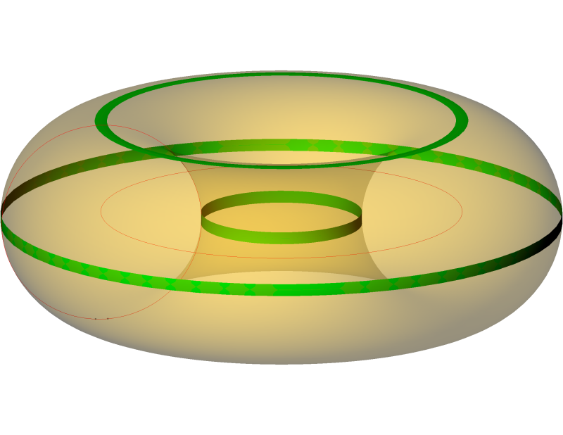
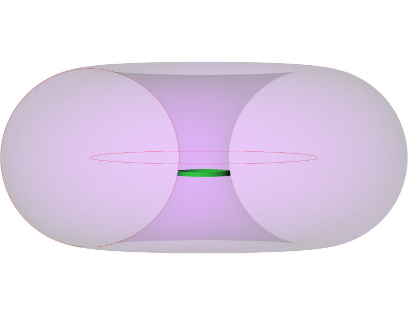
We are currently dealing with an issue where I work and it is regarding the degrees of freedom constrained by a toroidal datum feature used as primary. To be specific, it's not an entire torus, it's just about 7 degrees of the subsidiary radius but all 360 degrees of the main radius. It seems to me that this constrains 5 degrees of freedom but unlike a cone, there is a point and a plane, not a point and an axis, from which to take measurements from. My idea is that the thing that constrains u and v rotations is the spine of the torus but I'm getting some resistance to it.

What are your thoughts?

John Acosta, GDTP Senior Level
Manufacturing Engineering Tech
SSG, U.S. Army
Taji, Iraq OIF II
 
Replies continue below

Recommended for you

It's under the general, and incompletely unexplained, mathematically defined surfaces. See section 4-13.
 
powerhound,

A toroidal surface would constrain 5 degrees of freedom if used as a primary datum feature. All but the 3rd "clocking" rotation would be constrained.

I'm not quite sure what is meant by the "main radius" and "subsidiary radius" - can you clarify?

The datum feature simulator would be a perfect inverse toroidal surface. The datum is less clear - the toroid doesn't fit exactly into any of the feature types shown in Fig. 4-3 of Y14.5-2009. The closest one is (e) with the axis-and-point datum, even though the feature isn't conical. You could also use a point-and plane datum, or an axis-and-plane datum (provided that the axis is perpendicular to the plane). At the end of the day, the important thing is that the datum constrains the correct degrees of freedom of the coordinate system - in this case, everything except rotation about the "axis" of the toroid.

Evan Janeshewski

Axymetrix Quality Engineering Inc.
 
The main radius would be the radius of the spine of the donut and the subsidiary radius is the radius of the cross section of the extrusion. This is what Calypso calls the features anyway.

I don't see that a torus would have an axis which is why I'm kind of hung up on the point-plane scenario, but I see your point about what the datum actually is. That's the reason for this post. I'm inclined to recommend a change to the drawing simply for purposes of being able to repeatably check the features as well as not requiring a CMM to check it but that would get away from the actual function. This is one of those cases where dimensioning and tolerancing exactly according to function results in a difficult--and unreliable, IMHO--inspection.


John Acosta, GDTP Senior Level
Manufacturing Engineering Tech
SSG, U.S. Army
Taji, Iraq OIF II
 
Any non-cylindrical surface of revolution requires an axis and can be located be a point on that axis. The inverse is also true.

Cylinders have translational similarity so, alone, they can't be located along an axis.

Spheres have rotational similarity so, alone, they can't orient an axis.

Cones, toroids, hyperboloids, et al, define an axis and a point, and from those a plane that is normal to the axis passing through the point can be established. Planes through the axis and normal to each other exist, but aren't clocked until a 6th degree of freedom constraint is added.


Typically the derived datums are those which can be used to define the shape in the first place, as modified by their position in the hierarchy.
 
I don't think an axis is absolutely necessary for a torus because the spine is a circle and the center of a circle is a point but I'll think more on that.

So in terms of what I'm dealing with, if we treat a torus in the same way as a cone then it's the axis that constains rotation about X and Y. I'm having a hard time visualizing how that's possible since the simulator in that case would just be a cylinder--either external or internal. That will not constrain 5 degrees of freedom, as you already mentioned. In my opinion it really won't even repeatably constrain 4 because the TGC of the torus against a simulator is still just a circle. This is another reason for my idea that it is a plane and a point, and not an axis and a point, that constrains 5 degrees of freedom.

I'm not trying to be argumentative, I really am trying to solve a problem and I'm presenting my reasoning for my thoughts.

Thanks for participating.

John Acosta, GDTP Senior Level
Manufacturing Engineering Tech
SSG, U.S. Army
Taji, Iraq OIF II
 
Why would the simulator be a cylinder? The simulator would be a matching surface of revolution with a known axis and a locating point.

Mathematically a point/plane and point/axis are interchangeable. In most cases it is easiest to fully describe a plane in point-normal form; the coordinates of a point the plane passes through and a vector normal to the plane. Much easier to deal with than axis intercept form, which can't handle planes that are perpendicular to an axis (because they never intercept the other two axes)
 
Agreed. While the two may be mathematically interchangeable, GD&T-wise they are not. One constrains u and v rotations with an axis while the other constrains them with a plane that is perpendicular to this perceived axis. This affects how a secondary datum is interpreted.

John Acosta, GDTP Senior Level
Manufacturing Engineering Tech
SSG, U.S. Army
Taji, Iraq OIF II
 
Perhaps this is not exactly how ASME phrases things, but here's how I look at it:

Rotation and translation are not constrained by points, planes, or axes, but by the relationship between the actual part surfaces and the datum feature simulators. Based on the datum feature simulators you can construct a coordinate system to take measurements in. Depending on the datum feature references, the coordinate system may or may not be completely constrained relative to the part.

If you have only one rotational DOF unconstrained, you can still construct certain geometry that is fixed relative to the part: an axis (at the correct orientation and location), points (anywhere on the axis), and planes (perpendicular to the axis). I think the point+plane and point+axis options are equivalent both mathematically and GD&T-wise, but I find the concept of a complete but partially unconstrained coordinate system is much more useful instead.

In the case of your partial torus, I'm not sure exactly how the datum feature simulator would work. Which 7 degrees of the subsidiary radius are used? How is the surface toleranced? Is the datum feature referenced RMB, MMB, LMB, or BSC? Some or all of these aspects might affect the answer.

- pylfrm
 
pylfrm,

I think that your comments are right on the money, and I look at it in the same way. The contact between the simulators and the datum features constrains the part - the datums (points, planes, and axes) do not.

I'm also wondering about which 7 degrees of the toroid are involved, and how this part feature actually interfaces with the mating part.

John,

I've sketched a toroid with a three different 7-degree sectors shown in green - at the "top", "inside" and "outside". Which one is most like your part feature?

7_Degree_Toroid_Sections_ftxwur.png


Because 7 degrees is such a small fraction of the toroid, none of these would constrain all 5 of the degrees of freedom reliably - perhaps this is the source of the disagreement over the appropriate datum. The "top" feature is almost planar and would not constrain x and y translation well at all. The "inside" and "outside" features are almost circular and would not constrain u and v rotation or z translation well. This is a case where the theoretical constraint and the real constraint probably don't match very well. Technically, the feature constrains 5 degrees of freedom, but only 2 or 3 are fully constrained and the others are "weakly constrained". Y14.5 does not currently address these situations well.

Evan Janeshewski

Axymetrix Quality Engineering Inc.
 
It's more like the inner but moved down, and thus out, a little. Also, I was wrong about the 7 degrees. It's actually 3 degrees. The cross section diameter (like o-ring cross section) is 10 inches and the spine diameter is 12.780 inches. With such a tiny piece of the torus and such a large radius, the surface pretty much looks conical. If you created the torus with these specs and moved the center sector down .885 inches from the center of the torus to the center of the sector, you would have my datum feature.

I guess we'll just have to work our issues out and see where we land.

John Acosta, GDTP Senior Level
Manufacturing Engineering Tech
SSG, U.S. Army
Taji, Iraq OIF II
 
Yup. That's it!

John Acosta, GDTP Senior Level
Manufacturing Engineering Tech
SSG, U.S. Army
Taji, Iraq OIF II
 
Status
Not open for further replies.

Part and Inventory Search

Sponsor