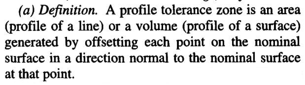
Hi All,
Great discussion!
3DDave,
I have also thought that some of these anomalies are caused by the part being modeled with sharp corners, which is fundamentally unrealistic. If the part is modeled with a tiny radius at each corner, this changes things a lot.
CH,
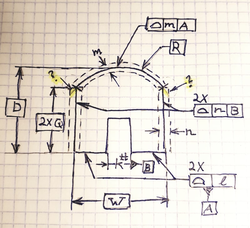
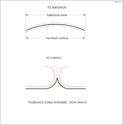
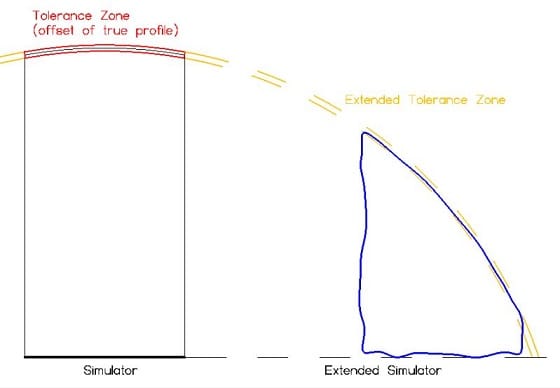
I'm not insisting that the tolerance zone can be extended to the degree shown in my sketch. I don't think that it should be allowed to extend that far, but I'm trying to come up with a reason why not.
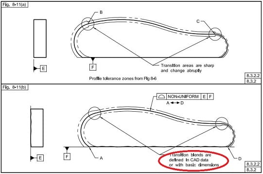
You brought up the issue of tolerance zones being independent. I generally support the idea that tolerances are independent of each other, and that we should be able to assess conformance to a tolerance independently of the other tolerances. Unfortunately, I think that if I follow this principle with tolerance zone extension it will lead to a conclusion I don't like ;^). If tolerances are independent, then we should be able to assess conformance to the profile tolerance on the upper surface in my figure, without knowing anything about the side surfaces. Or in Burunduk's figure, we should be able to evaluate the profile tolerance on the curved surface independently of the profile tolerance on the upper planar surface.
Does this mean that when assessing conformance to a tolerance, we pretend that we have no idea what the extent of the feature is? So that we must extend the tolerance zone boundaries to whatever extent the feature might have?
Burunduk,
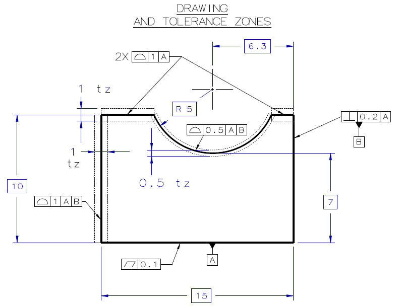
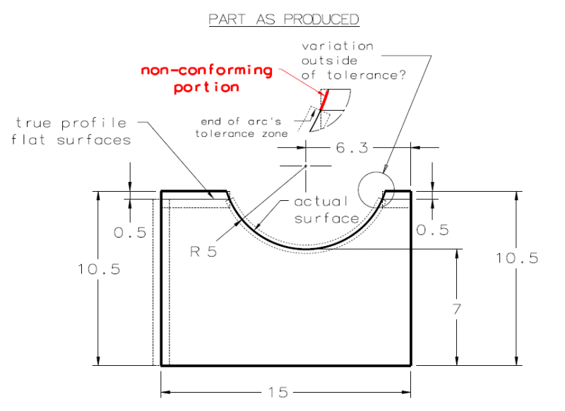
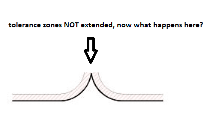
Your figures capture the issue quite well. If the arc tolerance zone does not extend, then the red segment would be nonconforming (which seems wrong). What would happen if the red section extended even further? It would technically be within the extended arc-shaped zone, but outside of the planar zone. Would we say that the part conforms to the arc-shaped zone but not the planar zone? I believe that we would.
We have to deal with extent for other tolerance zone types as well. For a position tolerance on a cylindrical hole, what is the extent of the position zone, when the actual thickness of the part could be greater than the as-modeled thickness? I believe there is some reference to the thickness of the part - we don't cut off the zone at its nominal extent.
chez311,
You could be right - we may just have to accept that "strange" things can happen if we specify tolerances that have insufficient constraints or apply in different datum reference frames.
Evan Janeshewski
Axymetrix Quality Engineering Inc.
")