Continue to Site

Eng-Tips is the largest engineering community on the Internet

Intelligent Work Forums for Engineering Professionals

  • Congratulations waross on being selected by the Eng-Tips community for having the most helpful posts in the forums last week. Way to Go!

Tolerance Zone Extent 2

Status
Not open for further replies.

axym

Industrial
Apr 28, 2003
1,043
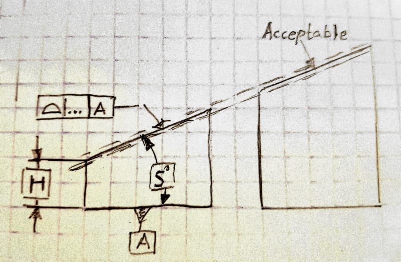
The recent thread on Surface Profile and Size brought up an interesting effect regarding tolerance zone extent.

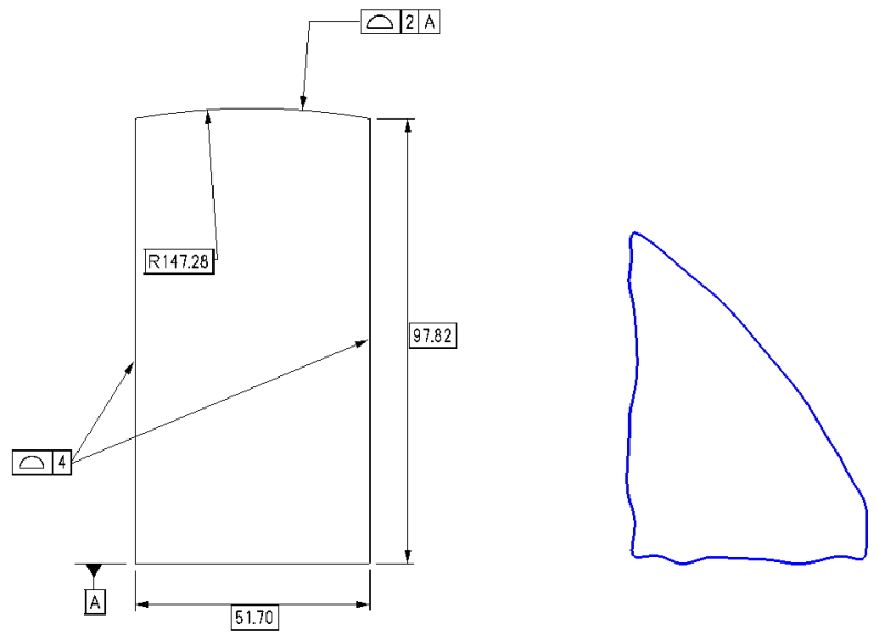
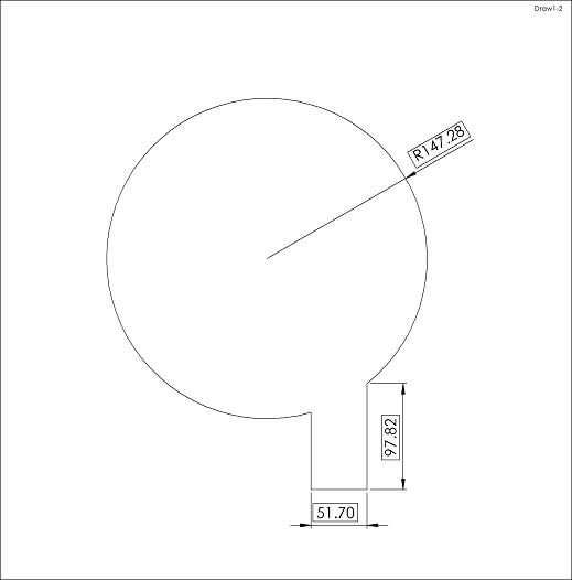
Here is a drawing for a fictitious part, that illustrates the effect. I have intentionally avoided the use of directly toleranced dimensions.

ExtendedProfile_nidtde.png


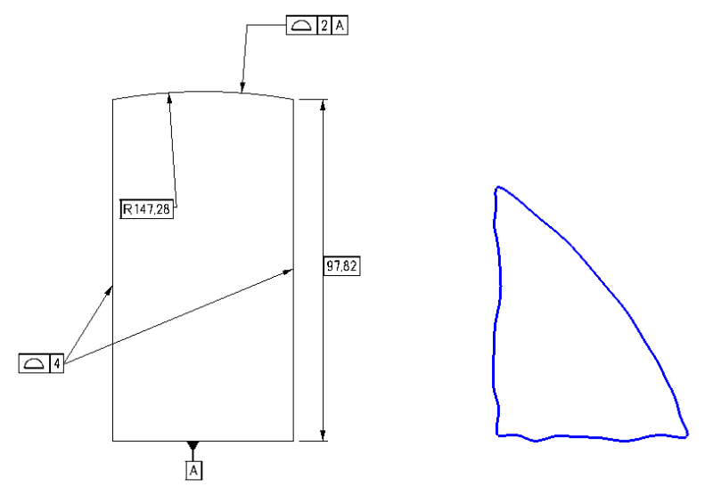
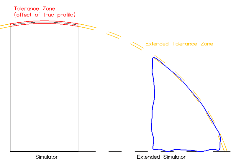
It has been proposed that an as-produced part like the blue one would conform to the 2 mm profile tolerance to A. This doesn't seem right to me, but so far I can't point to anything in Y14.5 that would disallow this. The standard does not give much detail on the extend of tolerance zones (or datum feature simulators).

Opinions?

Evan Janeshewski

Axymetrix Quality Engineering Inc.
 
Replies continue below

Recommended for you

Your part is under-defined.

It's like creating triangle with only 2 dimensions.

There is nothing in Y14.5 that would disallow that either.

"For every expert there is an equal and opposite expert"
Arthur C. Clarke Profiles of the future

 
If your blue arc is the R147.28 (with its profile zone rotated, as proposed in the other thread), then that creates a problem for one of the vertical sides that was meant to have a 4 mm zone. The right-hand vertical side is no longer there.
Or are we just ignoring that for now, and discussing the arc's orientation?
 
Tolerance zone extent can never prevent accepting undesired geometry if the true profile and datum reference frame are not properly defined.

Another example:

20200629_232045_g1rmcw.jpg
 
CH,

Right, I forgot the basic width.

J-P,

Yes, I cut the RHS so low that it's no longer there. That wasn't intentional - please ignore that for now.

Burunduk,

The planar feature example is a good one as well. That one has the effect of making the basic height irrelevant - the tilted surface could have any height and still pass.

I wonder if this just a property of certain geometry, that can occur if we define the sides completely independently of the top and bottom. Or is there a way that the effect can be prevented or limited? Is seems that allowing this kind of extension doesn't really reflect reality.

Evan Janeshewski

Axymetrix Quality Engineering Inc.
 
Hi All,
Here is a corrected version of the figure, with the basic width dimension and discernible side surface:

ExtendedProfile2_fvmzng.png


Evan Janeshewski

Axymetrix Quality Engineering Inc.
 
The closest thing I can find in the standard is paragraph 11.4.1 (and Fig. 11-15). With my emphasis, it says that "the tolerance zone is constrained in all three translational degrees of freedom and two rotational degrees of freedom relative to the referenced datum features."

Let's ignore the error at the end of that statement (the zone's DOFs are constrained relative to the datums, not the datum features). But it does say that the zone is what is constrained. Not where the feature must lie?
 
J-P,

I would say that the tolerance zone constraints are well understood - I don't see a problem there.

The problem is more in the extent of the tolerance zone, and possibly in the extent of the datum feature simulator:

ExtendedProfile3_awpsln.png


The tolerance zone is defined by boundaries that are normal offsets from the true profile. So the feature isn't really in the "original" tolerance zone, it is in the extended tolerance zone. Similarly, the datum feature simulator must be extended much farther than the extent of the basic datum feature. So the datum feature really isn't in contact with the "original" simulator, it's in contact with the extended simulator.

I wonder if it makes sense to allow the feature to lie within a zone that is nowhere near the original zone, and rest on a simulator that is nowhere near the original simulator.

Evan Janeshewski

Axymetrix Quality Engineering Inc.
 
Since the arc is in a different DRF than the sides there is no connection between them, any more than if there was a hole in the face of the part solely constrained with a position tolerance to the same DRF.

There is also no drafting/layout construction limitation to it either, a factor to the previous example. It's a peculiar situation because, yet again, there is no function in a real part that would require this tolerancing scheme.
 
axym said:
I wonder if this just a property of certain geometry, that can occur if we define the sides completely independently of the top and bottom. Or is there a way that the effect can be prevented or limited?

The only way to prevent this effect is to define the datum reference frame and the true profile properly. If we apply the profile control on the top face only and want the basic height H in the sketch I posted to be meaningful, the profile control should reference the left side vertical surface as a datum feature.
 
Eliminating the reference to datum feature A would also work, presuming a third arrow was added to indicate the bottom surface. There is more than one way to approach this; making it more complicated isn't the best one, particularly without knowing the function the surfaces are intended to serve.
 
Evan,

I think CH is right on the money - the example you have shown is unconstrained, or underconstrained. In fact, in addition to not having a location constraint between the sides and the arc, or of each to a common datum feature - the sides are datumless so they have no orientation constraint. They could rotate relative to A and the arc to show a similar case to your extended tolerance zone on the right without sides perpendicular to A. All sorts of weird behavior is possible when we leave DOF free like that, to your point I don't think theres anything that prohibits it.
 
Axym,

You still missing at least two dimensions:

Draw1_giumdl.jpg


"For every expert there is an equal and opposite expert"
Arthur C. Clarke Profiles of the future
 
All,

So are we saying that this is okay too? It's from Fig. 8-4 of Y14.5-2009.

Fig_8-4_Dwg_With_Extended_Means_This_f5db99.png


Evan Janeshewski

Axymetrix Quality Engineering Inc.
 
axym,
The feature should probably be rejected because it misses some elements of the geometry such as the peak at the left side on the true profile - perhaps it is like the issue that was brought up by Belanger regarding your figure in the first post here - geometry missing from the part. Usually, parts undergo some sort of visual inspection to see if the general shape matches what is on the drawing. I don't know if it is required by any standard though.

However, in principle, there is no prevention that some unexpected geometry can be approved for the exact same reason that causes this effect.
The curved true profile and the tolerance zone which is disposed about it could be programmed into the software of some measurement machine and "curvature-extrapolated" by any amount. The tool path that will be used for machining this will also be programmed as an extrapolation of the theoretical geometry. Since nothing constrains the tolerance zone relative to the side ends of the part right-left on the view, the entire feature can be produced "offset" relative to the width of the part with some elements of the extrapolation replacing the expected geometry at one side and with the other side of the curved profile trimmed, AND pass inspection.

When defining a geometry like that on a drawing, measures should be taken to prevent the acceptance of undesired geometry that results from that effect.
If only datum A is to be referenced for the profile control that is specified for the curved top as in the figure in the standard, the side faces should also be controlled by profile tolerance that references A, creating a simultaneous requirement that will minimize the phenomenon.
 
There is no mysterious "effect". Just missing dimensions. In case of illustration in Standard - intentionally incomplete.

Part1_b2qrvk.jpg


I said it before and I say it again - MATH is a 4-letter word in GD&T world.

"For every expert there is an equal and opposite expert"
Arthur C. Clarke Profiles of the future
 
CheckerHater,
Your profile tolerance acts as an angularity control with reference to A.
I hope you are not thinking that the feature does not conform to the profile requirement because the bottom-left angle came out obtuse instead of acute.
 
Evan,

In as much as intent matters - I'd say your "or this" on (30 Jun 20 16:31) clearly violates the design intent. So too would CH's (30 Jun 20 13:34) in my mind. While perhaps not explicitly stated one way or the other, I think its important to consider what would be rationally acceptable. While I don't think anyone would look at an actual part produced like your right feature on (30 Jun 20 01:58) and consider that acceptable, something between that and nominal (likely much closer to nominal) might be.

Obviously as noted before this all stems from a specification with insufficient constraint. I don't think we're going to find a passage or figure in the standard which explicitly states this behavior is acceptable or not - it would be up to the designer to ensure their drawing does not allow such strange behavior.

What might be a question which dives more into the gray area, at least for me, than your (30 Jun 20 16:31) would be a similar feature but instead something where the true profile is defined regardless of its extent - say a mathematically defined surface sin(x). The free translational DOF relative to the sides might be desirable, as it might not be such a concern how the surface is bounded on either side (ie: ends at two peaks, a peak and a trough, or anywhere in between) but so long as the top surface conforms to sin(x).
 
CH,

I don't think that it is juat a matter of missing dimensions. The intent in my example was that the basic part geometry is fully defined, either via reference to the CAD model or sufficient basic dimensions on the drawing. The tolerance zone extension issue still exists, even when the basic part geometry is fully defined.

Burunduk,

I agree that referencing one of the sides as a secondary datum feature (or creating a sim reqt) prevents the part from passing all of the tolerances in the condition I showed.

I don't think that we can really enforce anything when it comes to missing "elements" of the geometry. The model can have a sharp corner, and the actual part can have a rounded corner as long as the surface is within its tolerance zone.

chez311,

I agree that there isn't much control of the two side surfaces. I had intended to add a 2X above the 4 mm profile tolerance, to at least make the sides roughly parallel to each other. Or maybe I'll add 2X and a perpendicularity tolerance to A, to open another can of worms ;^).

I agree that the part I showed would violate design intent. The issue is how to rigorously define "rationally acceptable" and somehow allow a reasonable amount of zone extension (as in the Y14.5 means this figure) and not allow an unreasonable amount (as in my figure).

Evan Janeshewski

Axymetrix Quality Engineering Inc.
 
I agree with axym that missing dimensions are not the essence of the problem here.

For example, if the only modification made to fig. 8-4 posted by axym at 30 Jun 20 16:31 was adding basic height dimensions from datum feature A to the right side corner and the left side corner of the curved top, and also basically defining the entire shape of the curve, that still would not resolve the issue shown in the "Or this" portion, or a less exaggerated version of it that could have a reasonable potential to be approved.

However, I also do not think that the problem here is the tolerance zone extent. As noted there are tools the designer should use to properly define the geometry namely specifying sufficient datum references or invoking a simultaneous requirement. Not using these tools is not a good practice. It would not make sense to me if the standard attempted to prevent the issue by limiting the extension of the tolerance zone.
 
Status
Not open for further replies.

Part and Inventory Search

Sponsor