RealSaladsamurai
Mechanical
Hello All -
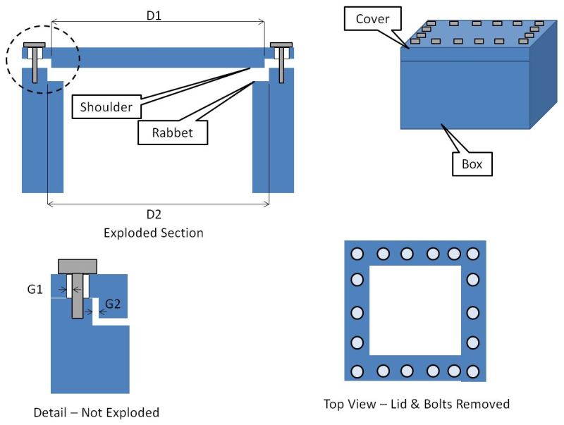
I am trying to do a tolerance stackup on an assembly to insure that it meets its design intent. In the attached image is a schematic of the assembly. It is essentially a box with a cover bolted to it. It's function is to hold a test article hanging from the lid during a vibration test. Note that the "box" is in fact a weldment made up of four walls welded together.
In the Section and detail view, you can see that the cover has a shoulder that rests in a rabbet style groove in the box. The idea is that during testing, if/when the lid shifts left/right and up/down due to vibrations, the shoulder will take the loading instead of the bolts. This means that the gap G2 between the shoulder and rabbet-wall should always be smaller than the gap G1 between the bolt and the clearance hole in the cover. That way, the shoulder will always strike the wall and the bolt will never contact the inside of the thru hole.
I will walk through what I have done so far, but note that my confusion mainly stems from what happens when we introduce a composite position.
Again, the problem statement is to ensure that G2 MAX is always less than G1 MIN
Calculate G2 MAX
G2 MAX = (D2 MAX)-(D1 MIN)
Calculate G1 MIN
To calculate G1 MIN, I calculate the Virtual Condition of the thru hole (VC_H) in the cover. I then calculate the VC of the fastener (VC_F) in the box (the weldment) and then take the difference.
My confusion is what to use for the value of T_H and T_F?
Both are positioned using a composite positional tolerance and so there is an upper feature control frame (FCF) that gives the feature locating tolerance of .021 and there is a lower FCF that gives the feature relating tolerance of .005.
I cannot seem to wrap my head around which one of these effects the gap size ... my gut is telling me that only the locating tolerance of .021 matters, but I could use a little guidance on this.
Thank you for looking.
________________________
FEMAP v11.1.0
MSC Nastran v2013
I am trying to do a tolerance stackup on an assembly to insure that it meets its design intent. In the attached image is a schematic of the assembly. It is essentially a box with a cover bolted to it. It's function is to hold a test article hanging from the lid during a vibration test. Note that the "box" is in fact a weldment made up of four walls welded together.
In the Section and detail view, you can see that the cover has a shoulder that rests in a rabbet style groove in the box. The idea is that during testing, if/when the lid shifts left/right and up/down due to vibrations, the shoulder will take the loading instead of the bolts. This means that the gap G2 between the shoulder and rabbet-wall should always be smaller than the gap G1 between the bolt and the clearance hole in the cover. That way, the shoulder will always strike the wall and the bolt will never contact the inside of the thru hole.
I will walk through what I have done so far, but note that my confusion mainly stems from what happens when we introduce a composite position.
Again, the problem statement is to ensure that G2 MAX is always less than G1 MIN
Calculate G2 MAX
G2 MAX = (D2 MAX)-(D1 MIN)
Calculate G1 MIN
To calculate G1 MIN, I calculate the Virtual Condition of the thru hole (VC_H) in the cover. I then calculate the VC of the fastener (VC_F) in the box (the weldment) and then take the difference.
Calculate VC_H
VC_H = D - T_H
Calculate VC_F
From appendix B.5 of ASME 14.5 2009 (derived from fixed fastener formula when no projected tolerance zone is used):
VC_F = F + T_F*(1+2P/D)
Calculate G1 MIN = VC_H - VC_F
VC_H = D - T_H
where:
D = MMC thru hole diameter
T_H = tolerance of position of thru hole
D = MMC thru hole diameter
T_H = tolerance of position of thru hole
Calculate VC_F
From appendix B.5 of ASME 14.5 2009 (derived from fixed fastener formula when no projected tolerance zone is used):
VC_F = F + T_F*(1+2P/D)
where:
F = MMC fastener diameter
T_F = positional tolerance of tapped hole
P = maximum thickness of thru hole (cover)
D = minimum depth of tapped hole
F = MMC fastener diameter
T_F = positional tolerance of tapped hole
P = maximum thickness of thru hole (cover)
D = minimum depth of tapped hole
Calculate G1 MIN = VC_H - VC_F
My confusion is what to use for the value of T_H and T_F?
Both are positioned using a composite positional tolerance and so there is an upper feature control frame (FCF) that gives the feature locating tolerance of .021 and there is a lower FCF that gives the feature relating tolerance of .005.
I cannot seem to wrap my head around which one of these effects the gap size ... my gut is telling me that only the locating tolerance of .021 matters, but I could use a little guidance on this.
Thank you for looking.
________________________
FEMAP v11.1.0
MSC Nastran v2013
")