Hi everyone
At the beginning I want to admit, that English is not my main language. I want to apologize for any uncertainties.
Units:mm
I was asked about possibility of making a functional gage.
There is s slice from the technical drawing:
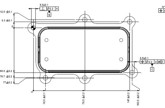
I understand, that because of RFS Material Condition Modifier placed in feature control frame of datum B, i need to use equipment (some expanding kind of pin, spring pin or tapered pin) which are capable of locating axis of the hole.
Now: Datum C hole feature control frame may be read as follows: The axis of the hole must be positioned within a cylindrical tolerance zone of 0.2 [mm] diameter at RFS. The tolerance zone is perpendicular to datum A, located down from datum B at it's MMC and over from datum B at it's MMC.
What I don't understand is how to sum up this two tolerances: one from feature control frame and another from line dimension tolerance.
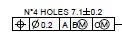
The other four holes are described as:
Is it even possible to make functional gage for this, or am I wasting my time?
There are no basic dimensions on drawing, is it correct for gd&t dimensioning ?
Best regards,
Jan
At the beginning I want to admit, that English is not my main language. I want to apologize for any uncertainties.
Units:mm
I was asked about possibility of making a functional gage.
There is s slice from the technical drawing:
I understand, that because of RFS Material Condition Modifier placed in feature control frame of datum B, i need to use equipment (some expanding kind of pin, spring pin or tapered pin) which are capable of locating axis of the hole.
Now: Datum C hole feature control frame may be read as follows: The axis of the hole must be positioned within a cylindrical tolerance zone of 0.2 [mm] diameter at RFS. The tolerance zone is perpendicular to datum A, located down from datum B at it's MMC and over from datum B at it's MMC.
What I don't understand is how to sum up this two tolerances: one from feature control frame and another from line dimension tolerance.
The other four holes are described as:
Is it even possible to make functional gage for this, or am I wasting my time?
There are no basic dimensions on drawing, is it correct for gd&t dimensioning ?
Best regards,
Jan
")