Continue to Site

Eng-Tips is the largest engineering community on the Internet

Intelligent Work Forums for Engineering Professionals

  • Congratulations waross on being selected by the Eng-Tips community for having the most helpful posts in the forums last week. Way to Go!

The possibility of making a functional gauge 4

Status
Not open for further replies.

Jan Lurka

Mechanical
Apr 30, 2020
3
Hi everyone
At the beginning I want to admit, that English is not my main language. I want to apologize for any uncertainties.
Units:mm

I was asked about possibility of making a functional gage.

There is s slice from the technical drawing:
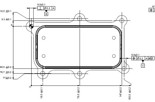
P1_tkdbac.jpg


I understand, that because of RFS Material Condition Modifier placed in feature control frame of datum B, i need to use equipment (some expanding kind of pin, spring pin or tapered pin) which are capable of locating axis of the hole.

Now: Datum C hole feature control frame may be read as follows: The axis of the hole must be positioned within a cylindrical tolerance zone of 0.2 [mm] diameter at RFS. The tolerance zone is perpendicular to datum A, located down from datum B at it's MMC and over from datum B at it's MMC.

What I don't understand is how to sum up this two tolerances: one from feature control frame and another from line dimension tolerance.

The other four holes are described as:

P2_wi6dty.jpg


Is it even possible to make functional gage for this, or am I wasting my time?
There are no basic dimensions on drawing, is it correct for gd&t dimensioning ?

Best regards,
Jan
 
Replies continue below

Recommended for you

It can be done. But it will br more expensive.

Also carefully consider the rrasons you arr not allowing MMC. Does it really matter that much?
 
What standard are you using?

There are no basic dimensions on drawing, is it correct for gd&t dimensioning ?

In short - no. Position tolerance combined with +/- direct tolerancing of location is not a valid combination in ASME and cannot be evaluated. I am quite confident it is a similar story in ISO.

From the ASME Y14.5-2018 appendix:

Y14.5-2018 Mandatory Appendix I para I-2 said:
Tolerances directly applied to location dimensions for regular features of size were removed from this dimensioning and tolerancing Standard in 1982, and they are not included in the alternative practices in this Appendix. There is no defined meaning in this Standard for a tolerance that is directly applied to a location dimension that applies to a regular feature of size.

With this in mind, while an RFS functional/hard gauge is certainly complex and expensive as TheTick noted (MMC would be much easier and more representative of function in most cases) - the combination of +/- location and position tolerances makes it impossible to evaluate according to the standard. Its wholly up to individual interpretation as to what it should look like.
 
TheTick said:
It can be done. But it will br more expensive.

Also carefully consider the rrasons you arr not allowing MMC. Does it really matter that much?

The problem is, that I am not author of this drawing. I can't decide if it is at MMC or not.

chez311 said:
What standard are you using?

Drawing was made in ISO 8015


It's a completely invalid position specification. You must have basic dimensions locating C. Plus, you need at least one more "clocking" datum, I don't think it's A but we can't see A. But since B is perpendicular to A I think A is in the plane of the view. You can't inspect this drawing with any gauging, send it back.

----------------------------------------

The Help for this program was created in Windows Help format, which depends on a feature that isn't included in this version of Windows.
 
dgallup said:
Plus, you need at least one more "clocking" datum, I don't think it's A but we can't see A. But since B is perpendicular to A I think A is in the plane of the view.

You are right - datum A is in the plane of the view, it's base of this part.

So now I should send back this drawing with adnotation what they need to do:

1. Consider allowing MMC
2. Line dimensions change from toleranced to basic

am I right?

Thank you all for your helpful answers.
 
Customers are not always right. Time for sone dialog.

Give them a quote for the gage with GD&T as-is. Also prepare a second quote along with changes to the GD&T.

Money talks. Sometimes it teaches.
 
ISO or ASME, as it was previously said, a functional gage (with fixed size gage elements) cannot be used if (M) modifier does not follow the tolerance value in the tolerance frame and if the dimensions used to define nominal location of features are not basic (in ISO they are called theoretically exact).

Also, it looks like the size callouts for features B and C are missing diameter symbols.
 
OP said:
Drawing was made in ISO 8015

Pmarc,

Since it's an ISO drawing, maybe has an E (circled) somewhere, so MMC(edit)R on the position is "not recommended" (you know :"reduces technical and economical advantages of MMR and LMR concepts" ISO 2692:2014).

How would you circumvent this issue? I guess the designer want to follow the ISO standards to the letter of the law, then this is the price to pay?

Also, from previous discussions :
"If a FOS is controlled with a size tolerance only and then is referenced at MMR in the datum portion of a geometric tolerance, for some reason ISO says that maximum material virtual size is equal to the MMS size of the feature.This means that in such case the envelope requirement is imposed to the datum feature even though the envelope requirement has not been explicitly specified on the face of the drawing."

Since B and C are modified at MMR in the FCF, then (even if my initial assumption of E (circled) being present somewhere on the face of the drawing is wrong) the envelope requirement is still enforced thus no MMR (M modifier in the FCF to help gaging)

Could you, please, when you get a chance clarify my lack of ISO understanding.

 
greenimi said:
Since it's an ISO drawing, maybe has an E (circled) somewhere
ISO 8015 was actually ISO's way of invoking the envelope principle. So no circled E needed.

John-Paul Belanger
Certified Sr. GD&T Professional
Geometric Learning Systems
 
Belanger said:
ISO 8015 was actually ISO's way of invoking the envelope principle. So no circled E needed.

Could you, please indicate where (which standard) this statement came from?
J-P,
I know you have a good reputation here, but I am not really sure if this statement is correct.
Please correct me if I am wrong saying that you are wrong:):)


Ooops --- you're right. I had it backwards; 8015 is the one that required the circled E (if you want to invoke the envelope principle). Next time I'll actually check the standard before I go from memory!
I formerly did a lot of work with a German company, and I was thinking of the old DIN 7167 standard, which was an automatic envelope rule.

John-Paul Belanger
Certified Sr. GD&T Professional
Geometric Learning Systems
 
greenimi,

The statement from ISO 2692 says that use of (E) usually reduces technical and economical advantages of Maximum Material Requirement. So it is rather the other way around.
 
pmarc said:
use of (E) usually reduces technical and economical advantages of Maximum Material Requirement. So it is rather the other way around.

So, it's only one way street?
If MMR is functional requirement then we have to get rid of default circled E by adding LP. Am I correct?

If yes, it is important if we add LP close to the upper size dimension or to the lower size dimension or does not matter ?
6.6
6.4 LP

or

6.6 LP
6.4

for datum feature B feature of size.


pmarc,

Why am I asking because I am trying to learn the usage of GN and GX and I would like to know if it's important if GN or GX are added close to the upper size limit or to the lower size limit and if would make any difference so, I extended the same question to the LP usage.

Thank you again pmarc
 
No. If MMR is the functional requirement, one can still apply (E) modifier if she/he thinks it adds any value. The mentioned statement from 2692 does not prohibit this.

Regardless, the rules for application of GN, GX and LP modifiers are defined in ISO 14405-1:2016. I would say there are a couple of things that matter in case of the specification you gave, that is 6.6 over 6.4.

First one is that if there is only a single special operator (modifier), it applies to both limits, regardless if shown in the upper or lower line of the size specification.

Secondly, if two different special operators are to be used, they should be specified in the line to which they apply. So 6.6 LP over 6.4 GX means that local two-point size requirement applies to the 6.6 size limit, and that the 6.4 limit applies to the size of maximum inscribed associated feature. This is equivalent to the envelope requirement applied to a hole or slot.

6.6 GN over 6.4 LP means that the 6.6 limit applies to the size of minimum circumsribed associated feature, and that local two-point size requirement applies to the 6.4 size limit. This, in turn, is equivalent to the envelope requirement applied to a cylinder or tab.

I know, it is not easy and clear. But believe me, this is not the worst thing that ISO has to offer.
 
Status
Not open for further replies.

Part and Inventory Search

Sponsor