Continue to Site

Eng-Tips is the largest engineering community on the Internet

Intelligent Work Forums for Engineering Professionals

  • Congratulations KootK on being selected by the Eng-Tips community for having the most helpful posts in the forums last week. Way to Go!

Temperature (thermal) loads on industrial structures (ambient temp change)

Status
Not open for further replies.

mic_str

Structural
Nov 13, 2019
3
Hello Folks!

I am a big fan of this forum, read a lot, but this is my first thread :)
I did some small forum search on thermal action but couldn't find proper thread.

My point of focus are industrial structures (not pipe racks) exposed on ambient temperature change (day/night/seasonal).
I am talking about eg. support structures for heavy equipment like silos, filters, condensers etc.

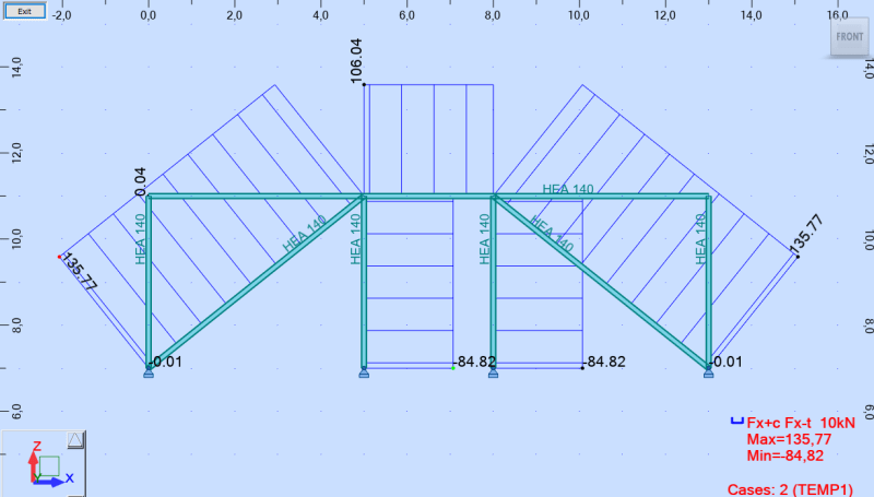
The basic thing is that all of those structures are exposed on ambient temp change. In Europe where I live (according to Eurocode) assembly temp equals 8C degreed. Winter -30, Summer +30. Temp change delta -38/+22. For stiff, well braced structure it generates huge normal forces in members + some significant pulling and horizontal force on foundations (bracing bays).

The issue with pipe racks is quite simple. They are designed to allow deformation etc. but what are your engineering good practices for structures that should be stiff and strong enough to carry a lot of equipment load (weight, wind).
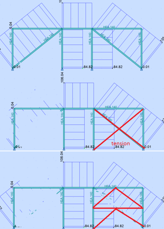
Some projects I have seen had an assumption that structure has a capacity to slip on a bolt connections and compensate thermal expansions but I do not buy it. On the other hand normal force from temp looks ridiculously big for bracing members and beams which cannot deform due to bracing bays.

I would be grateful for some assist and your experience share.

Thank you!
 
Replies continue below

Recommended for you

I can't comment directly on your question, but this is probably worth a view.

"Expansion Joints in Buildings" - Technical Report No. 65

"Programming today is a race between software engineers striving to build bigger and better idiot-proof programs, and the Universe trying to produce bigger and better idiots. So far, the Universe is winning."
 
Have you accounted for the connecting members expanding/contracting along with the brace? This is assuming all are exposed to the same temperature change.

 
When the expansion length is significantly longer than the braced bay then this is indeed an issue to be looked at more closely. (Though not one I'm an expert in.)

EG if a builing looks like this |x|~|~|~|~|~|~|x| with braced bays at each end then you can readily have elongation with the braced bays fighting each other... This isn't exactly and uncommon configuration. You can ignore it for a while but when things get big enough or stiff enough you it might be worth considering.

Instead |~|~|~|x|x|~|~|~| contains the same latereral bracing but without the same expansion issue.
 
Thank you guys!


rowingengineer said:
"Expansion Joints in Buildings" - Technical Report No. 65
The structures I am looking at are not the one to use expansion joints to, eg. steel support structure for silo 200 tons. The structure is like 15x15m on a plan.

bootlegend said:
Have you accounted for the connecting members expanding/contracting along with the brace? This is assuming all are exposed to the same temperature change.
Yes, all members are subjected to temp gradient

human909 said:
When the expansion length is significantly longer than the braced bay then this is indeed an issue to be looked at more closely. (Though not one I'm an expert in.)
Yes, the trick works well on buildings or pipe racks. But my point of concern are structures more stiff and rather not significant in plan, as I mentioned above.


Basically my question was rather to know your practises and engineering experience in this matter, cause have heard lot of different stories :)
Ambient temp change on structures courses sometimes significant internal member forces + huge force on anchor joints. Just please look at screen attached. Small frame, all pinned joints, HEA140, only load is temp gradient +30. Internal forces ridicules. Nodal displacements due to expansion max 0.3mm!

scr_dojiqv.png


Some time ago I was in oil and gas business and we did a lot of marine offshore structures, and for almost all of deck houses and other framing structures on rigs and platforms no temp load was accounted. 90% of structures were welded -> stiff as hell :)
 
IMO the forces that your analysis says occur due to ambient temperature changes in braced frames do not really occur in real life. My thinking:
1) These are self limiting forces. If there structure is allowed to deform a little, the force goes away.
2) You've got a little slop in your bolts. If you get some bolt slip, you get your deflection and the force goes away.
3) We have our column bases modeled as infinitely rigid supports. That's not true. If you replace this in your analysis with something more realistic, you'll see some very slight movement that prevents those thermal forces from developing.
 
Mic_str:
Rather than locking everything in place, by your base (foundation) and joint fixities, look at the problem from a geometric standpoint. The whole structure expands or contracts due to the same temp. differential, and if you are talking about a .3mm joint movement, that’s well within the fab. tolerances of bolt hole placement, member lengths, etc. The middle structure increases in height due to the two columns expanding. And, the top beam increases in length about the same amount as the space btwn. the two found. points, they may be a bit cooler. In any case, the middle structure (two cols. and beam) all change in proportion to their original length, so they don’t really stress each other much. This center structure tends to rotate the left triangular braced frame counter clockwise and the right triangular braced frame clockwise a little bit, but still, all in proportion to their original lengths. Work out the new geometry, and to several decimal places, you can’t even see it, at .3mm node movement. You may induce a little moment at the triangular brace frame bases if they are truly infinitely fixed. Look again at how you’ve modeled your structure. Human909’s first example shows a long string of beams expanding btwn. two brace points, and this can be a problem. Alternatively, his second example provides the same amount of brace support on that beam line, but allows the expansion to happen without any problem. Of course, sufficient expansion would cause problems with window glass, openings and finishes under that beam line.
 
In my experience, most of the large temp forces present in analysis results can be dealt with bracing concept change (if possible..mostly it is).
Try these 2 variants that I have attached and see the force change.

Untitled_vrenka.png
 
mic_str said:
Yes, the trick works well on buildings or pipe racks. But my point of concern are structures more stiff and rather not significant in plan, as I mentioned above.
we
For stiff structures that are squat like the one you have shown it really isn't a problem. Nodal displacements of 0.3mm! Forget about it. Your structure isn't THAT stiff.

For what it is worth. I've been busy with silo support structures for 1600tonne.
 
For storage tanks in ambient-temperature service, including leg-supported or pedestal-supported, this is generally not a consideration. "no temp load was accounted. 90% of structures were welded -> stiff as hell" sums up the situation there. A lot of times, it's not that stiff, really, but still, much experience shows no problems there.
For flat-bottom tanks in heated service, there are some provisions in the design codes based on industry experience.
For some small leg-supported tanks in heated service, I've designed slip joints similar to those used in piping supports to reduce thermal stresses to a reasonable level. The main issue in these cases is there does not seem to be any consensus on how (or if!) the problem should be handled.
 
Wow, really appreciate discussion and all the suggestions :)

Screen I have posted is not a case of any original structure. It was only to visualize the problem.
Playing with brace arrangement helps. The best solution is to keep one brace for whole structure, than normal force from temp tends to 0 or implement some slotted connection in the middle beam.

Now my thoughts are to look at the displacements at first and then make some judgments if this is really a matter.
For my original structure normal stresses are a result of nodal displacements of 1.3mm. After all I think structure will lose it, especially considering the case it might be assembled within bigger fabrication and installation tolerances.

Thank you and if you have any more ideas please share :)

 
Status
Not open for further replies.

Part and Inventory Search

Sponsor